


FC8600-UM-251-9370 7-11
7 ADJUSTMENT
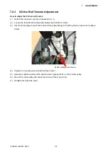
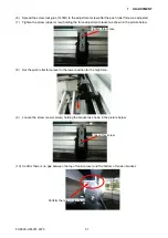
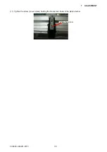
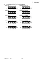
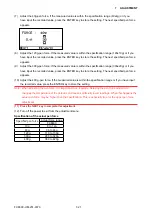
(10) Loosen the lower position adjustment screw, and then gently tighten the lower position adjustment
screw until the screw hit to the inside of parts.
Don’t tighten this screw strongly.
Top part of the bracket will be bent if you tighten this screw strongly.
Lower position adjustment screw
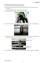
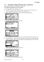
(11)
Confirm there is no gap between the top of tension and the bottom of tension bracket.
Confirm here there is no gap
between the top of tension and
the bottom of tension bracket.
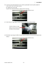
(12) Spread the screw-lock-glue (1401B) to the lower position adjustment screw after the lower position was
adjusted.
Lower position adjustment screw
Summary of Contents for FC8600-100
Page 1: ...CUTTING PLOTTER SERVICE MANUAL FC8600 60 75 100 130 160 FC8600 UM 251 07 9370 ...
Page 2: ......
Page 4: ...FC8600 UM 251 9370 II ...
Page 32: ......
Page 103: ...FC8600 UM 251 9370 7 43 7 ADJUSTMENT ...
Page 124: ...FC8600 UM 251 9370 9 2 9 PARTS LIST Outer Casing 4 6 2 3 9 13 11 12 14 15 10 1 16 8 7 5 ...
Page 141: ...FC8600 UM 251 9370 10 3 10 BLOCK DIAGRAMS AND CIRCUIT DIAGRAMS 10 2 2 Main Board CONNECTOR ...
Page 142: ...FC8600 UM 251 9370 10 4 10 BLOCK DIAGRAMS AND CIRCUIT DIAGRAMS 10 2 3 Main Board MOTOR DRIVER ...
Page 143: ...FC8600 UM 251 9370 10 5 10 BLOCK DIAGRAMS AND CIRCUIT DIAGRAMS 10 2 4 Main Board FPGA ...
Page 144: ...FC8600 UM 251 9370 10 6 10 BLOCK DIAGRAMS AND CIRCUIT DIAGRAMS 10 2 5 Main Board I F ...
Page 145: ...FC8600 UM 251 9370 10 7 10 BLOCK DIAGRAMS AND CIRCUIT DIAGRAMS 10 2 6 Main Board MEMORY ...
Page 147: ...FC8600 UM 251 9370 10 9 10 BLOCK DIAGRAMS AND CIRCUIT DIAGRAMS 10 2 8 LAN Board ...
Page 148: ...FC8600 UM 251 9370 10 10 10 BLOCK DIAGRAMS AND CIRCUIT DIAGRAMS 10 2 9 Light Pointer ...
Page 149: ...FC8600 UM 251 9370 10 11 10 BLOCK DIAGRAMS AND CIRCUIT DIAGRAMS 10 2 10Pen Relay Board ...
Page 151: ...FC8600 UM 251 9370 10 13 10 BLOCK DIAGRAMS AND CIRCUIT DIAGRAMS 10 2 13Control Panel Board ...
Page 152: ...FC8600 UM 251 9370 10 14 10 BLOCK DIAGRAMS AND CIRCUIT DIAGRAMS 10 2 14Cam Sensor Board ...


