FC8600-UM-251-9370 I
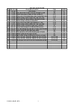
HISTORY OF REVISIONS
No. Date issued
Description of revision
Page
Edition
1
13.2.22
First Printing
All
01
2
14.6.18
The rank of items 10 and 15, 16 were changed to A rank.
9-8
02
3
14.6.18
Parts name was corrected for item number 35.
9-11
02
4
14.6.18
The rank of Pinch Roller Base was changed to B rank.
9-10
02
5
14.6.18
Parts number of Drive Pulley Assy was corrected.
9-11
02
6
14.6.18
The rank of I/F Panel LAN was changed to D rank.
9-1
02
7
14.6.18
Parts number of End Cap was added.
9-15
02
8
14.6.18
The rank of Cam Shaft was changed to C rank.
9-10
02
9
14.7.23
Parts number of Drive Pulley Assy was corrected.
9-10
03
10
14.8.27
Parts number of Center Covers were corrected.
9-1
04
11
14.8.27
Quantity of Push Roller Positioning Label S for the FC8600-60 and FC8600-75 were corrected.
9-14
04
12
14.8.27
The rank of labels were changed to C rank except I/F labels.
9-14
04
13
14.11.18
Parts number for LED Base was added.
9-4
05
14
14.11.18
The construction of Pen Block Assembly was corrected.
9-5
05
15
15.02.24 Parts number for Fan was corrected.
9-1
05
16
15.04.28 Item number of Paper Hold down A and B were corrected.
9-6
05
17
15.05.21 The procedure of distance adjustment was corrected.
7-22 to 7-24
05
18
15.08.04 The procedure of distance adjustment was corrected.
7-23 to 7-24
06
19
15.10.20 The procedure of the Tool 2 and the Cross Cutter Threshold adjustment was added.
7-40 to 7-41
07
Summary of Contents for FC8600-100
Page 1: ...CUTTING PLOTTER SERVICE MANUAL FC8600 60 75 100 130 160 FC8600 UM 251 07 9370 ...
Page 2: ......
Page 4: ...FC8600 UM 251 9370 II ...
Page 32: ......
Page 103: ...FC8600 UM 251 9370 7 43 7 ADJUSTMENT ...
Page 124: ...FC8600 UM 251 9370 9 2 9 PARTS LIST Outer Casing 4 6 2 3 9 13 11 12 14 15 10 1 16 8 7 5 ...
Page 141: ...FC8600 UM 251 9370 10 3 10 BLOCK DIAGRAMS AND CIRCUIT DIAGRAMS 10 2 2 Main Board CONNECTOR ...
Page 142: ...FC8600 UM 251 9370 10 4 10 BLOCK DIAGRAMS AND CIRCUIT DIAGRAMS 10 2 3 Main Board MOTOR DRIVER ...
Page 143: ...FC8600 UM 251 9370 10 5 10 BLOCK DIAGRAMS AND CIRCUIT DIAGRAMS 10 2 4 Main Board FPGA ...
Page 144: ...FC8600 UM 251 9370 10 6 10 BLOCK DIAGRAMS AND CIRCUIT DIAGRAMS 10 2 5 Main Board I F ...
Page 145: ...FC8600 UM 251 9370 10 7 10 BLOCK DIAGRAMS AND CIRCUIT DIAGRAMS 10 2 6 Main Board MEMORY ...
Page 147: ...FC8600 UM 251 9370 10 9 10 BLOCK DIAGRAMS AND CIRCUIT DIAGRAMS 10 2 8 LAN Board ...
Page 148: ...FC8600 UM 251 9370 10 10 10 BLOCK DIAGRAMS AND CIRCUIT DIAGRAMS 10 2 9 Light Pointer ...
Page 149: ...FC8600 UM 251 9370 10 11 10 BLOCK DIAGRAMS AND CIRCUIT DIAGRAMS 10 2 10Pen Relay Board ...
Page 151: ...FC8600 UM 251 9370 10 13 10 BLOCK DIAGRAMS AND CIRCUIT DIAGRAMS 10 2 13Control Panel Board ...
Page 152: ...FC8600 UM 251 9370 10 14 10 BLOCK DIAGRAMS AND CIRCUIT DIAGRAMS 10 2 14Cam Sensor Board ...

