FC8600-UM-251-9370 IV
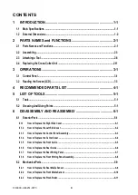
6.2.4 How to Replace the Control Panel Board and the LCD .....................................................................6-12
6.2.5 How to Replace the Pen Block ............................................................................................................6-13
6.2.6 How to Replace the Y-belt ....................................................................................................................6-15
6.2.7 How to Replace the Pinch Roller Sensor ............................................................................................6-17
6.2.8 How to Replace the Y-relay Board.......................................................................................................6-19
6.2.9 How to Replace the Cam Sensor ........................................................................................................ 6-20
6.2.10 How to Replace the Y-motor ............................................................................................................... 6-21
6.2.11 How to Replace the X-motor ............................................................................................................... 6-22
6.2.12 How to Replace the Main Board ......................................................................................................... 6-23
6.2.13 How to Replace the Vacuum Fan........................................................................................................ 6-24
6.2.14 How to Replace the Drive Roller......................................................................................................... 6-25
6.2.15 How to Replace the Cutting Mat ......................................................................................................... 6-27
6.2.16 Home Dog Position .............................................................................................................................. 6-28
6.2.17 Cross Cutter Dog Position .................................................................................................................. 6-28
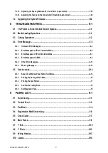
7 ADJUSTMENTS ..........................................................................7-1
7.1 List of Items Requiring Readjustment .................................................................................7-1
7.2 Mechanical Adjustments .......................................................................................................7-2
7.2.1 Y-Belt Tension Adjustment ....................................................................................................................7-2
7.2.2 Y-Drive Belt Tension Adjustment ..........................................................................................................7-3
7.2.3 X-Drive Belt Tension Adjustment ..........................................................................................................7-4
7.2.4 Pinch Roller Pressure Adjustment ........................................................................................................7-5
7.3.1 DIP Switch Settings ..............................................................................................................................7-13
7.3.2 Explanation of the Values of the Main Board Settings .....................................................................7-15
7.3.3 Clearing the Non-Volatile RAM ............................................................................................................7-16
7.3.4 How to Enter the Adjustment Menu ....................................................................................................7-18
7.3.5 Adjusting the Pen Force .......................................................................................................................7-20
7.3.6 Adjusting the Distance Accuracy ........................................................................................................7-22
7.3.7 Adjusting the Registration Mark Sensor Sensitivity .........................................................................7-25
7.3.8 Adjusting the Offset of the Auto-Registration Mark Sensor ............................................................7-26
7.3.9 Adjusting the Cross Cutter Home Position ........................................................................................7-28
7.3.10 Adjusting the Offset of the Light Pointer Position ............................................................................7-30
7.3.11 Confirming the 2-Pen Model (2-pen model) .......................................................................................7-32
7.3.12 Adjusting the Pen Exchange Y Direction Value (2-pen model) ........................................................7-34
Summary of Contents for FC8600-100
Page 1: ...CUTTING PLOTTER SERVICE MANUAL FC8600 60 75 100 130 160 FC8600 UM 251 07 9370 ...
Page 2: ......
Page 4: ...FC8600 UM 251 9370 II ...
Page 32: ......
Page 103: ...FC8600 UM 251 9370 7 43 7 ADJUSTMENT ...
Page 124: ...FC8600 UM 251 9370 9 2 9 PARTS LIST Outer Casing 4 6 2 3 9 13 11 12 14 15 10 1 16 8 7 5 ...
Page 141: ...FC8600 UM 251 9370 10 3 10 BLOCK DIAGRAMS AND CIRCUIT DIAGRAMS 10 2 2 Main Board CONNECTOR ...
Page 142: ...FC8600 UM 251 9370 10 4 10 BLOCK DIAGRAMS AND CIRCUIT DIAGRAMS 10 2 3 Main Board MOTOR DRIVER ...
Page 143: ...FC8600 UM 251 9370 10 5 10 BLOCK DIAGRAMS AND CIRCUIT DIAGRAMS 10 2 4 Main Board FPGA ...
Page 144: ...FC8600 UM 251 9370 10 6 10 BLOCK DIAGRAMS AND CIRCUIT DIAGRAMS 10 2 5 Main Board I F ...
Page 145: ...FC8600 UM 251 9370 10 7 10 BLOCK DIAGRAMS AND CIRCUIT DIAGRAMS 10 2 6 Main Board MEMORY ...
Page 147: ...FC8600 UM 251 9370 10 9 10 BLOCK DIAGRAMS AND CIRCUIT DIAGRAMS 10 2 8 LAN Board ...
Page 148: ...FC8600 UM 251 9370 10 10 10 BLOCK DIAGRAMS AND CIRCUIT DIAGRAMS 10 2 9 Light Pointer ...
Page 149: ...FC8600 UM 251 9370 10 11 10 BLOCK DIAGRAMS AND CIRCUIT DIAGRAMS 10 2 10Pen Relay Board ...
Page 151: ...FC8600 UM 251 9370 10 13 10 BLOCK DIAGRAMS AND CIRCUIT DIAGRAMS 10 2 13Control Panel Board ...
Page 152: ...FC8600 UM 251 9370 10 14 10 BLOCK DIAGRAMS AND CIRCUIT DIAGRAMS 10 2 14Cam Sensor Board ...

