FC8600-UM-251-9370 III
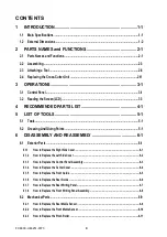
CONTENTS
1 INTRODUCTION .........................................................................1-1
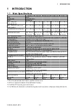
1.1 Main Specifications ...............................................................................................................1-1
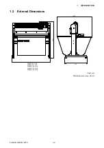
1.2 External Dimensions ............................................................................................................ 1-2
2 PARTS NAMES and FUNCTIONS ............................................ 2-1
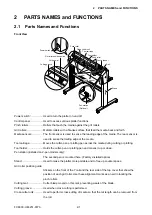
2.1 Parts Names and Functions ..................................................................................................2-1
2.2 Assembling ............................................................................................................................2-3
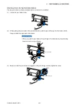
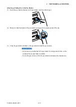
2.3 Attaching a Tool ....................................................................................................................2-8
2.4 Replacing the Cross-Cutter Unit ........................................................................................2-11
3 OPERATIONS ............................................................................ 3-1
3.1 Control Panel ......................................................................................................................... 3-1
3.2 Reading the Screen (LCD) ....................................................................................................3-3
4 RECOMMENDED PARTS LIST ................................................. 4-1
5 LIST OF TOOLS ........................................................................ 5-1
6 DISASSEMBLY AND REASSEMBLY ....................................... 6-1
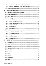
6.1.1 How to Replace the Right Side Cover .................................................................................................. 6-1
6.1.2 How to Replace the Left Side Cover .................................................................................................... 6-2
6.1.3 How to Replace the Control Panel Assembly .....................................................................................6-3
6.1.4 How to Replace the Center Cover ........................................................................................................6-4
6.1.5 How to Replace the Front Guide ..........................................................................................................6-5
6.1.6 How to Replace the Rear Guide ...........................................................................................................6-6
6.1.7 How to Replace the Rear Writing Panel ............................................................................................... 6-7
6.1.8 How to Replace the Front Writing Panel Assembly ............................................................................6-8
6.2.1 How to Replace the Rear Media Sensor ..............................................................................................6-9
6.2.2 How to Replace the Front Media Sensor ............................................................................................6-10
6.2.3 How to Replace the Pinch Roller .........................................................................................................6-11
Summary of Contents for FC8600-100
Page 1: ...CUTTING PLOTTER SERVICE MANUAL FC8600 60 75 100 130 160 FC8600 UM 251 07 9370 ...
Page 2: ......
Page 4: ...FC8600 UM 251 9370 II ...
Page 32: ......
Page 103: ...FC8600 UM 251 9370 7 43 7 ADJUSTMENT ...
Page 124: ...FC8600 UM 251 9370 9 2 9 PARTS LIST Outer Casing 4 6 2 3 9 13 11 12 14 15 10 1 16 8 7 5 ...
Page 141: ...FC8600 UM 251 9370 10 3 10 BLOCK DIAGRAMS AND CIRCUIT DIAGRAMS 10 2 2 Main Board CONNECTOR ...
Page 142: ...FC8600 UM 251 9370 10 4 10 BLOCK DIAGRAMS AND CIRCUIT DIAGRAMS 10 2 3 Main Board MOTOR DRIVER ...
Page 143: ...FC8600 UM 251 9370 10 5 10 BLOCK DIAGRAMS AND CIRCUIT DIAGRAMS 10 2 4 Main Board FPGA ...
Page 144: ...FC8600 UM 251 9370 10 6 10 BLOCK DIAGRAMS AND CIRCUIT DIAGRAMS 10 2 5 Main Board I F ...
Page 145: ...FC8600 UM 251 9370 10 7 10 BLOCK DIAGRAMS AND CIRCUIT DIAGRAMS 10 2 6 Main Board MEMORY ...
Page 147: ...FC8600 UM 251 9370 10 9 10 BLOCK DIAGRAMS AND CIRCUIT DIAGRAMS 10 2 8 LAN Board ...
Page 148: ...FC8600 UM 251 9370 10 10 10 BLOCK DIAGRAMS AND CIRCUIT DIAGRAMS 10 2 9 Light Pointer ...
Page 149: ...FC8600 UM 251 9370 10 11 10 BLOCK DIAGRAMS AND CIRCUIT DIAGRAMS 10 2 10Pen Relay Board ...
Page 151: ...FC8600 UM 251 9370 10 13 10 BLOCK DIAGRAMS AND CIRCUIT DIAGRAMS 10 2 13Control Panel Board ...
Page 152: ...FC8600 UM 251 9370 10 14 10 BLOCK DIAGRAMS AND CIRCUIT DIAGRAMS 10 2 14Cam Sensor Board ...

