FC8600-UM-251-9370 19
8 TROUBLESHOOTING
8.5.5
Self Diagnostic Test
Operation status can be tested by self diagnostic test by operating the sensors and switches following the
instruction on the screen.
Operation
(1)
Confirm that the power is turned off.
(2) Turn the power on without loading the media.
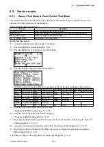
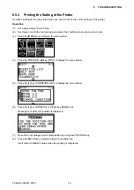
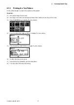
(3) Press the [MENU] key to display the menu below.
(4) Press the POSITION (
t
) key (TEST) to display the menu below.
(5) Press the [4] key (DIAGNOSTICS) to display the menu below.
(6) Press the [1] key (DONE).
The first testing menu is displayed. And follow the instructions on the menu.
(7)
Press the [1] key to continue to the next test, after you check the CAM lever sensor.
(8) The testing items are shown below.
1 Cam lever sensor
2 Home sensor
3 Push roller sensor
4 Rear media sensor
5 Font media sensor
6 X motor signal
7 Y motor signal
8 Tool height signal
9 [1] key
10 [2] key
11 [3] key
12 [4] key
13 POSITION [
u
] key
14 POSITION [
t
] key
15 POSITION [
q
] key
16 POSITION [
p
] key
17 [ENTER] key
18 [CONDITION] key
19 [ORIGIN] key
20 [FAST] key
21 [CROSS CUT] key
22 [COPY] key
23 [MENU] key
24 [STOP] key
(9) It will return to TEST menu screen once all the test items are completed.
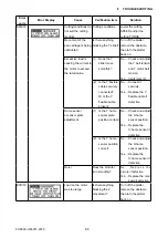
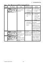
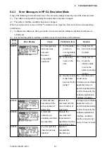
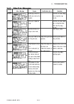
Summary of Contents for FC8600-100
Page 1: ...CUTTING PLOTTER SERVICE MANUAL FC8600 60 75 100 130 160 FC8600 UM 251 07 9370 ...
Page 2: ......
Page 4: ...FC8600 UM 251 9370 II ...
Page 32: ......
Page 103: ...FC8600 UM 251 9370 7 43 7 ADJUSTMENT ...
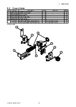
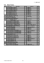
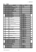
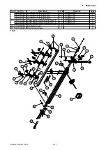
Page 124: ...FC8600 UM 251 9370 9 2 9 PARTS LIST Outer Casing 4 6 2 3 9 13 11 12 14 15 10 1 16 8 7 5 ...
Page 141: ...FC8600 UM 251 9370 10 3 10 BLOCK DIAGRAMS AND CIRCUIT DIAGRAMS 10 2 2 Main Board CONNECTOR ...
Page 142: ...FC8600 UM 251 9370 10 4 10 BLOCK DIAGRAMS AND CIRCUIT DIAGRAMS 10 2 3 Main Board MOTOR DRIVER ...
Page 143: ...FC8600 UM 251 9370 10 5 10 BLOCK DIAGRAMS AND CIRCUIT DIAGRAMS 10 2 4 Main Board FPGA ...
Page 144: ...FC8600 UM 251 9370 10 6 10 BLOCK DIAGRAMS AND CIRCUIT DIAGRAMS 10 2 5 Main Board I F ...
Page 145: ...FC8600 UM 251 9370 10 7 10 BLOCK DIAGRAMS AND CIRCUIT DIAGRAMS 10 2 6 Main Board MEMORY ...
Page 147: ...FC8600 UM 251 9370 10 9 10 BLOCK DIAGRAMS AND CIRCUIT DIAGRAMS 10 2 8 LAN Board ...
Page 148: ...FC8600 UM 251 9370 10 10 10 BLOCK DIAGRAMS AND CIRCUIT DIAGRAMS 10 2 9 Light Pointer ...
Page 149: ...FC8600 UM 251 9370 10 11 10 BLOCK DIAGRAMS AND CIRCUIT DIAGRAMS 10 2 10Pen Relay Board ...
Page 151: ...FC8600 UM 251 9370 10 13 10 BLOCK DIAGRAMS AND CIRCUIT DIAGRAMS 10 2 13Control Panel Board ...
Page 152: ...FC8600 UM 251 9370 10 14 10 BLOCK DIAGRAMS AND CIRCUIT DIAGRAMS 10 2 14Cam Sensor Board ...

