


FC8600-UM-251-9370 2-10
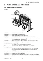
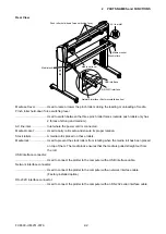
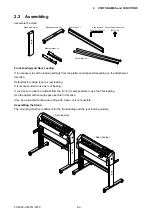
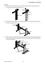
2 PARTS NAMES and FUNCTIONS
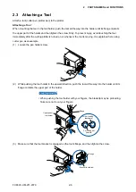
Attaching a Plotting Pen to the Pen Station
(1) Open the pen-hold mechanism on the pen station, and then attach a pen�
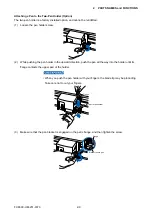
(2) Make sure that the bracket of the pen station is engaged in the upper groove of the pen�
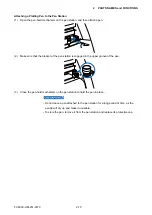
(3) Close the pen-hold mechanism on the pen station to hold the pen in place�
• Do not leave a pen attached to the pen station for a long period of time, as the
pen tip will dry up and make it unusable�
• To store the pen, remove it from the pen station and replace its protective cap�
Summary of Contents for FC8600-100
Page 1: ...CUTTING PLOTTER SERVICE MANUAL FC8600 60 75 100 130 160 FC8600 UM 251 07 9370 ...
Page 2: ......
Page 4: ...FC8600 UM 251 9370 II ...
Page 32: ......
Page 103: ...FC8600 UM 251 9370 7 43 7 ADJUSTMENT ...
Page 124: ...FC8600 UM 251 9370 9 2 9 PARTS LIST Outer Casing 4 6 2 3 9 13 11 12 14 15 10 1 16 8 7 5 ...
Page 141: ...FC8600 UM 251 9370 10 3 10 BLOCK DIAGRAMS AND CIRCUIT DIAGRAMS 10 2 2 Main Board CONNECTOR ...
Page 142: ...FC8600 UM 251 9370 10 4 10 BLOCK DIAGRAMS AND CIRCUIT DIAGRAMS 10 2 3 Main Board MOTOR DRIVER ...
Page 143: ...FC8600 UM 251 9370 10 5 10 BLOCK DIAGRAMS AND CIRCUIT DIAGRAMS 10 2 4 Main Board FPGA ...
Page 144: ...FC8600 UM 251 9370 10 6 10 BLOCK DIAGRAMS AND CIRCUIT DIAGRAMS 10 2 5 Main Board I F ...
Page 145: ...FC8600 UM 251 9370 10 7 10 BLOCK DIAGRAMS AND CIRCUIT DIAGRAMS 10 2 6 Main Board MEMORY ...
Page 147: ...FC8600 UM 251 9370 10 9 10 BLOCK DIAGRAMS AND CIRCUIT DIAGRAMS 10 2 8 LAN Board ...
Page 148: ...FC8600 UM 251 9370 10 10 10 BLOCK DIAGRAMS AND CIRCUIT DIAGRAMS 10 2 9 Light Pointer ...
Page 149: ...FC8600 UM 251 9370 10 11 10 BLOCK DIAGRAMS AND CIRCUIT DIAGRAMS 10 2 10Pen Relay Board ...
Page 151: ...FC8600 UM 251 9370 10 13 10 BLOCK DIAGRAMS AND CIRCUIT DIAGRAMS 10 2 13Control Panel Board ...
Page 152: ...FC8600 UM 251 9370 10 14 10 BLOCK DIAGRAMS AND CIRCUIT DIAGRAMS 10 2 14Cam Sensor Board ...


