


FC8600-UM-251-9370 2-9
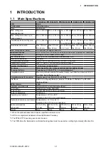
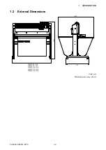
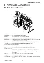
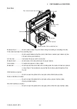
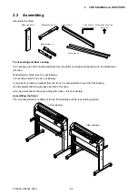
2 PARTS NAMES and FUNCTIONS
Attaching a Pen to the Two-Pen Holder (Option)
The two-pen holder is a factory-installed option, and cannot be retrofitted.
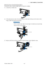
(1) Loosen the pen holder screw�
(2) While pushing the pen holder in the upward direction, push the pen all the way into the holder until its
flange contacts the upper part of the holder.
• When you push the pen holder with your fingers, the blade tip may be protruding.
Take care not to cut your fingers.
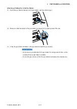
Flange
Upper part of pen holder
(3) Make sure that the pen bracket is engaged on the pen’s flange, and then tighten the screw.
Bracket to hold pen
Flange
Summary of Contents for FC8600-100
Page 1: ...CUTTING PLOTTER SERVICE MANUAL FC8600 60 75 100 130 160 FC8600 UM 251 07 9370 ...
Page 2: ......
Page 4: ...FC8600 UM 251 9370 II ...
Page 32: ......
Page 103: ...FC8600 UM 251 9370 7 43 7 ADJUSTMENT ...
Page 124: ...FC8600 UM 251 9370 9 2 9 PARTS LIST Outer Casing 4 6 2 3 9 13 11 12 14 15 10 1 16 8 7 5 ...
Page 141: ...FC8600 UM 251 9370 10 3 10 BLOCK DIAGRAMS AND CIRCUIT DIAGRAMS 10 2 2 Main Board CONNECTOR ...
Page 142: ...FC8600 UM 251 9370 10 4 10 BLOCK DIAGRAMS AND CIRCUIT DIAGRAMS 10 2 3 Main Board MOTOR DRIVER ...
Page 143: ...FC8600 UM 251 9370 10 5 10 BLOCK DIAGRAMS AND CIRCUIT DIAGRAMS 10 2 4 Main Board FPGA ...
Page 144: ...FC8600 UM 251 9370 10 6 10 BLOCK DIAGRAMS AND CIRCUIT DIAGRAMS 10 2 5 Main Board I F ...
Page 145: ...FC8600 UM 251 9370 10 7 10 BLOCK DIAGRAMS AND CIRCUIT DIAGRAMS 10 2 6 Main Board MEMORY ...
Page 147: ...FC8600 UM 251 9370 10 9 10 BLOCK DIAGRAMS AND CIRCUIT DIAGRAMS 10 2 8 LAN Board ...
Page 148: ...FC8600 UM 251 9370 10 10 10 BLOCK DIAGRAMS AND CIRCUIT DIAGRAMS 10 2 9 Light Pointer ...
Page 149: ...FC8600 UM 251 9370 10 11 10 BLOCK DIAGRAMS AND CIRCUIT DIAGRAMS 10 2 10Pen Relay Board ...
Page 151: ...FC8600 UM 251 9370 10 13 10 BLOCK DIAGRAMS AND CIRCUIT DIAGRAMS 10 2 13Control Panel Board ...
Page 152: ...FC8600 UM 251 9370 10 14 10 BLOCK DIAGRAMS AND CIRCUIT DIAGRAMS 10 2 14Cam Sensor Board ...


