31
30
Grange Machinery Ltd.
Sproatley Grange
Hull
HU11 4PT
M: 07918 515385
T: 01482 815711
E: [email protected]
W: www.grangemachinery.co.uk
Grange Machinery Ltd.
Sproatley Grange
Hull
HU11 4PT
M: 07918 515385
T: 01482 815711
E: [email protected]
W: www.grangemachinery.co.uk
Before undertaking maintenance on the Grange 3m LDT ensure
the following safety procedures are put in place.
i) Never undo hydraulic pipes until all the pressure is released.
ii) Identify whether the maintenance activity requires the
Grange 3m LDT equipment to be raised off the ground.
If so any 2nd stage cultivation/seeding equipment will need
to be safely uncoupled.
iii) Locate suitable hard standing which can take the full weight of
the Grange 3m LDT. If requiring the 3m LDT machine to be raised
off the ground, apply safe chocking methods, such as adjustable
axle stands with adequate load capacity. Refer to the equipment
specification; Section 5.0.
iv) Stop the movement controls of the tractor, apply the handbrake,
stop the engine and remove the key.
v) Wear appropriate PPE.
vi) Select the correct workshop tools.
vii) Remove any residual mud or other extraneous material from
the machine.
viii) Use lubrication spray oils to free up bolts to facilitate ease
of removal.
13.1 Replacing shear bolts
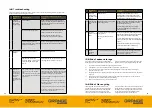
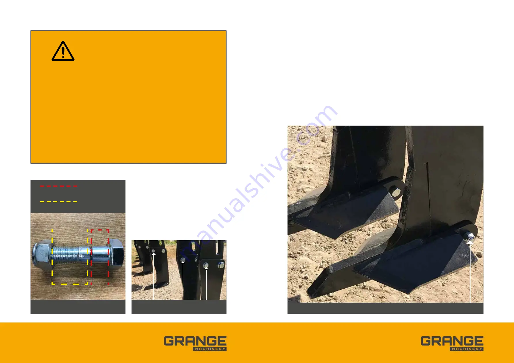
FIG 15.0 SHEAR BOLT WITH SHEAR PLANE
RED LINE – LOWER LEG (15MM)
YELLOW LINE – UPPER LEG (20MM)
FIG 16.0 SHEAR BOLT LOCATION
When replacing the points use suitable solid level
ground e.g. concrete/tarmac, to avoid the risk of
sinking and potential injuries whilst changing the
points as well as potential damage to tungsten
tipped points. The implement must be raised on the
tractor linkage and the tractor engine turned off and
handbrake applied.
It is important to support the weight of the Grange
3m LDT with appropriate axle stands to enable safe
access to the points. Please be aware it is forbidden
to work under a suspended load without the
adequate support.
Wear appropriate PPE which is safety glasses and
gloves. In addition the use of a safety bump cap will
prevent any inadvertent contact by your head with
the frame.
Once you are confident that you have met the safety
standards required you can proceed.
Unbolt the single fixing (M10 x 40mm long bolt) from
the worn point to free the point. A new point can
then be replaced into the same position using the
same size fixing. Ensure the bolt is fully tightened,
ref Fig 17.0.
When you have finished replacing the points,
remove the axle stands supports/chocks in order
to proceed.
13.2 Replacing points
FIG 17.0 NEW POINTS FITTED AND SECURING CONNECTIONS


