background image

9

SERVICE

REQUIRED TOOLS

Torque wrench

Bench vise, with soft jaws

Hammer

Rubber mallet

Razor or other sharp tool

8 mm (5/16 in.) dia. brass rod

8 mm, 11 mm, 15 mm, 25 mm,

3/4 in. and 7/8 in. open–end wrenches

17 mm box or socket wrench

22 mm crow’s–foot wrench

Adjustable wrenches

24 in. adjustable wrench

Thread lubricant

Anaerobic thread sealant

DISCONNECTING THE DISPLACEMENT PUMP

KEEP HANDS AND FINGERS AWAY FROM THE

PRIMING  PISTON DURING OPERA TION AND

WHENEVER THE PUMP IS CHARGED WITH AIR

to reduce the risk of injury! 

On the pump down-

stroke the priming piston extends beyond the intake

cylinder to pull the material into the pump. The prim-

ing piston works under extreme force. During opera-

tion and whenever the pump is charged with air, the

priming piston can severely injure or amputate a

hand or finger, or break a tool, caught between it and

the intake cylinder. Always follow the 

Pressure Re-

lief Procedure Warning

 on page 8, before check-

ing, clearing, cleaning, flushing or servicing any part

of the pump.

The air motor piston (located behind the air motor

plates) also moves when air is supplied to the motor.

NEVER operate the pump with the air motor plates

removed. Before servicing the pump, follow the

Pressure Relief Procedure Warning

 on page 8, to

prevent the pump from starting accidentally.

WARNING

1. Flush the pump if possible. Stop the pump at the bot-

tom of its stroke. Follow the

 Pressure Relief Proce-

dure Warning

 on page 8.

2. Disconnect the air hose. Hold the fluid outlet fitting

(7) with an adjustable wrench to keep it from being

loosened while you disconnect the fluid hose. Re-

move the pump from its mounting. Note the relative

position of the pump’s fluid outlet to the air motor’s air

inlet.

3. Using an adjustable wrench, unscrew the coupling

nut (104) from the connecting rod (103). Remove the

coupling collars (105). Take care not to lose or drop

them. See Fig 3.

4. Hold the tie rod flats with an 11 mm wrench to keep

them from turning. Use the wrench (1 13) provided

with the pump (or a 17 mm box or socket wrench) to

unscrew the tie rod locknuts (106) from the tie rods

(102). Carefully pull the displacement pump (107) off

the air motor (101).

5. Refer to page 10 for displacement pump service. To

service the air motor, refer to the separate air motor

manual, supplied.

RECONNECTING THE DISPLACEMENT PUMP

1. Orient the pump’s fluid outlet to the air motor’s air in-

let as was noted in step 2 under 

Disconnecting the

Displacement Pump. 

Position the displacement

pump (107) on the tie rods (102). See Fig 3.

NOTE:

If you removed the tie rods (102) from the air mo-

tor (101) or air motor adapter plate, reinstall

them using an 11 mm wrench. Torque the rods to

20–25 N.m (15–18 ft–lb) on Model 222–783, and

34–41 N.m (25–30 ft–lb) on Model 222–782.

2. Screw the locknuts (106) onto the tie rods (102) and

torque to 34–41 N.m (25–30 ft–lb), using the wrench

(113) provided (or a 17 mm box or socket wrench).

3. Place the coupling nut (104) on the displacement

rod, then place the coupling collars (105) in the nut.

Screw the coupling nut onto the connecting rod (103)

loosely. Hold the connecting rod flats with an adjust-

able wrench to keep it from turning. Using an adjust-

able wrench, torque the nut to 41–48 N.m (30–35 ft–

lb).

4. Using a torque wrench in the square hole of the

supplied wrench (113), torque the packing nut (2) to

27–34 N.m (20–25 ft–lb).

5. Mount the pump and reconnect all hoses. Reconnect

the ground wire if it was disconnected during repair.

Turn on the air to the motor and run the pump slowly.

6. Fill the packing nut/wet–cup 1/3 full of Graco Throat

Seal Liquid or compatible solvent.
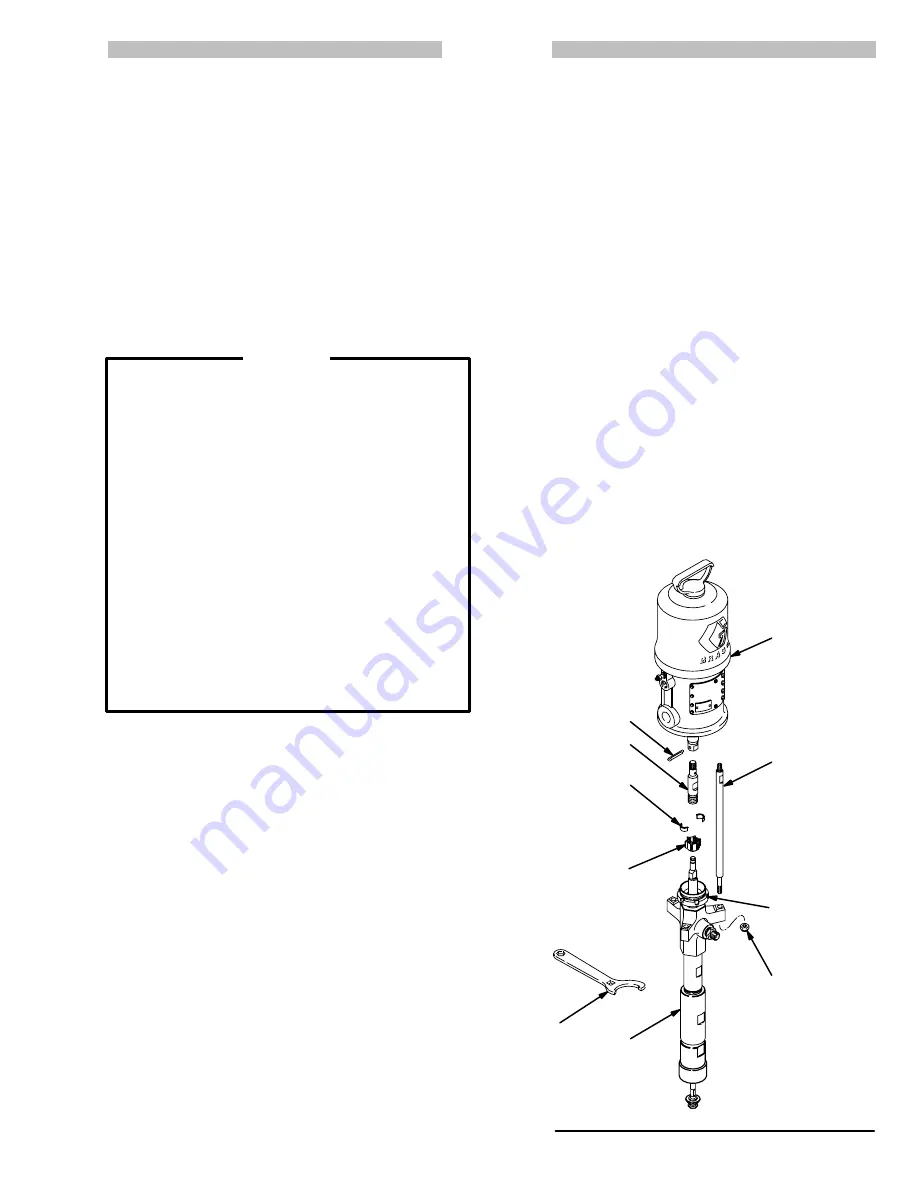
Fig 3

101

103

105

107

102

TORQUE TO

20–25 N.m 

(15–18 ft–lb)

ON MODEL

222–783;

34–41 N.m

(25–30 ft–lb)

ON MODEL

222–782

106

TORQUE TO

34–41 N.m 

(25–30 ft–lb)

104

TORQUE TO

41–48 N.m

 (30–35 ft–lb)

108

2

TORQUE TO

27–34 N.m 

(20–25 ft–lb)

0204A

113

Summary of Contents for Metric CHECK-MATE 200

Page 1: ...OX 1441 MINNEAPOLIS MN 55440 1441 COPYRIGHT 1991 GRACO INC TABLE OF CONTENTS Warnings 2 3 Terms 3 Typical Installation 4 Installation 5 Operation Maintenance 6 7 Service Troubleshooting Chart 8 Requir...

Page 2: ...Whenever you stop spraying dispensing even for a moment always set the spray gun dispensing valve safety latch in the closed or safe posi tion making the gun valve inoperative Failure to set the safe...

Page 3: ...is created by the high velocity flow of fluid through the pump and hose If every part of the spray dispensing equipment is not properly grounded sparking may occur and the system may become hazardous...

Page 4: ...Air Line Lubricator J Bleed Type Master Air Valve required for pump K Air Regulator L Air Line Filter M Bleed Type Master Air Valve for accessories N Fluid Drain Valve required P Fluid Pressure Regula...

Page 5: ...gallon ram Refer to Accessories on page 19 and the separate manuals included with the kits for further information Air Line Accessories Install the following accessories in the order shown in the Typ...

Page 6: ...pump starts Moving parts can pinch or amputate your fingers or other body parts When the pump is operating the priming piston 23 located at the pump intake and the air motor piston located behind the...

Page 7: ...he exposed displacement rod and damaging the throat packings Always flush the pump before the fluid dries on the dis placement rod Never leave water or water based fluid in the pump overnight First fl...

Page 8: ...mp Replace packings To determine if the fluid hose or gun is obstructed follow the Pressure Relief Procedure Warning below Disconnect the fluid hose and place a container at the pump fluid outlet to c...

Page 9: ...3 Remove the coupling collars 105 Take care not to lose or drop them See Fig 3 4 Hold the tie rod flats with an 11 mm wrench to keep them from turning Use the wrench 1 13 provided with the pump or a 1...

Page 10: ...king nut 2 throat packings 3 5 and glands 4 6 from the outlet housing 9 DO NOT remove the fluid outlet nipple 7 and o ring 8 from the outlet housing unless they need replace ment 10 Unscrew the bleede...

Page 11: ...QUE TO 21 27 N m 15 20 ft lb 21 TORQUE TO 34 41 N m 25 30 ft lb 4 5 6 3 LIPS OF V PACKINGS MUST FACE DOWN THROAT PACKING DETAIL 7 REMOVE ONLY IF DAMAGED TORQUE TO 70 75 N m 51 55 ft lb 11 TORQUE TO 17...

Page 12: ...ad lubricant to the bottom threads of the cylinder 11 Be sure the o ring 10 is in place on the cylinder Guide the intake valve housing 16 up onto the priming piston rod 21 Screw the valve housing onto...

Page 13: ...UE TO 170 185 N m 125 135 ft lb 15 TORQUE TO 21 27 N m 15 20 ft lb 21 TORQUE TO 34 41 N m 25 30 ft lb 4 5 6 3 LIPS OF V PACKINGS MUST FACE DOWN THROAT PACKING DETAIL 7 REMOVE ONLY IF DAMAGED TORQUE TO...

Page 14: ...O DESCRIPTION QTY 101 222 791 AIR MOTOR Monark See 307 043 for parts 1 102 184 076 ROD tie 295 mm 11 61 shoulder to shoulder 3 103 184 162 ROD adapter 1 104 184 100 NUT coupling 1 105 184 131 COLLAR c...

Page 15: ...istributor 6 digit Part Number Qty Part Description 101 103 105 107 102 TORQUE TO 20 25 N m 15 18 ft lb 106 TORQUE TO 34 41 N m 25 30 ft lb 104 TORQUE TO 41 48 N m 30 35 ft lb REF PART NO NO DESCRIPTI...

Page 16: ...TO 21 27 N m 15 20 ft lb 21 TORQUE TO 34 41 N m 25 30 ft lb 1 27 TORQUE TO 27 34 N m 20 25 ft lb 26 19 18 LARGE BEVEL MUST FACE DOWN 21 REF 24 23 FLAT SIDE MUST FACE UP 7 TORQUE TO 70 75 N m 51 55 ft...

Page 17: ...y Consists of Ref No Qty 8 1 10 2 14 1 19 1 26 1 41 1 222 785 THROAT PACKING REPAIR KIT Must be purchased separately Consists of Ref No Qty 3 2 4 1 5 3 6 1 222 786 THROAT PACKING CONVERSION KIT To con...

Page 18: ...LVE 215 362 12 bar 180 psi MAXIMUM WORKING PRESSURE Shuts off air supply to the pump if the pump accelerates beyond the pre adjusted setting due to an empty supply container interrupted fluid supply t...

Page 19: ...raise pump from 19 liter 5 gallon pails Release of air pressure and weight of the pump cause it to move downward Use with wiper plate 222 812 Also requires Cart Accessory Kit 224 376 Re fer to Instruc...

Page 20: ...Outlet Pressure bar psi at a specific fluid flow lpm gpm and operating air pressure bar psi 1 Locate desired flow along bottom of chart 2 Follow vertical line up to intersection with selected fluid ou...

Page 21: ...lpm gpm and air pressure bar psi 1 Locate desired flow along bottom of chart 2 Read vertical line up to intersection with selected air consumption curve gray Follow right to scale to read air consump...

Page 22: ...E OIL gpm liters min To find Fluid Outlet Pressure bar psi at a specific fluid flow lpm gpm and operating air pressure bar psi 1 Locate desired flow along bottom of chart 2 Follow vertical line up to...

Page 23: ...id flow lpm gpm and air pressure bar psi 1 Locate desired flow along bottom of chart 2 Read vertical line up to intersection with selected air consumption curve gray Follow right to scale to read air...

Page 24: ...A B C D Model 222 782 1147 mm 365 mm 782 mm 328 mm 45 2 in 14 35 in 30 8 in 12 9 in 222 783 1207 mm 418 mm 789 mm 328 mm 47 5 in 16 45 in 31 0 in 12 9 in DIMENSIONAL DRAWING Model 222 783 Shown A B C...

Page 25: ...22 782 MONARK PUMP 63 5 mm 2 50 22 2 mm 0 875 62 50 mm 2 461 38 5 mm 1 516 31 2 mm 1 230 54 1 mm 2 131 44 5 mm 1 750 7 1 mm 0 281 DIA 2 11 4 mm 0 449 DIA 3 63 5 mm 2 50 54 1 mm 2 130 31 25 mm 1 230 62...

Page 26: ...26 NOTES...

Page 27: ...27 NOTES...

Page 28: ...ade at a reasonable charge which charges may include the costs of parts labor and transportation DISCLAIMERS AND LIMITATIONS THE TERMS OF THIS WARRANTY CONSTITUTE PURCHASER S SOLE AND EXCLUSIVE REMEDY...

Page 29: ...109 and 113 Add Model 237 203 Monark Pump Items 101 106 108 109 110 and 113 are the same as for Model 222 782 Item 102 is 190 161 Tie Rod Item 103 is 237 252 Connecting Rod Items 104 and 105 are not u...

Reviews: