background image

Installation

Pre-Installation Procedure

1.

Relieve the pressure.

To reduce the risk of serious injury whenever you
are instructed to relieve pressure, always follow the
Pressure Relief Procedure above.

2.

Close the shut-off valve (item J in Fig. 1).

3.

Ground the hose and reel or console.   See
Grounding on page 6.   Do not use Teflon

 tape

on the pipe joints; it may cause a loss of ground
across the pipe joint.

Installation Procedure


If this is a new installation, or if the oil in the
lines is contaminated, flush the lines before you
install the metered valve.

1.

If this is an existing installation, go to step 7.

Steps 2 through 6 are the 

Flushing Procedure

.

2.

Close the fluid shut-off valve (J) at each dispense
position.

3.

Make sure the main fluid outlet valve at the pump
is closed, the air pressure to the pump motor is
adjusted, and the air valve is open.  Slowly open
main fluid valve.

4.

Place the hose end (with no dispense valve
connected) into a container for waste oil.  Secure
the hose in the container so it will not come out
during flushing.  If you have multiple dispense
positions, first flush the dispense position farthest
from the pump, and work your way toward the
pump.

5.

Slowly open the shut-off valve (J) at the dispense
position.  Flush out a sufficient amount of oil to
ensure that the entire system is clean, and close
the valve.

6.

Repeat step 5 at all other dispense positions.

7.

Relieve the pressure.

To reduce the risk of serious injury, whenever you
are instructed to relieve pressure, always follow the
Pressure Relief Procedure on page 4.

8.

Loosen and disconnect the hose from the old
dispense valve (the one that you are replacing).
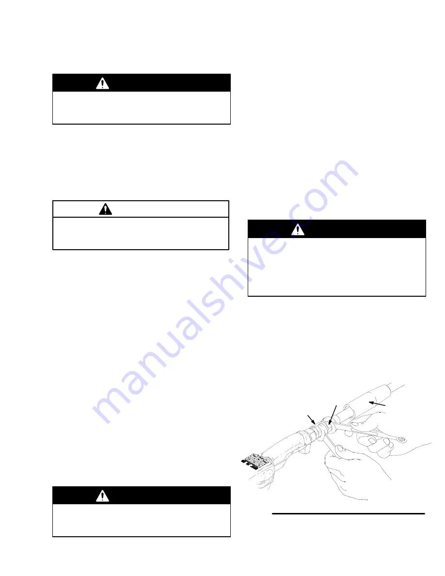
9.

Slide the swivel cover (4) onto the hose, small end
first.  See Fig. 3.

10. Apply thread sealant to the the male threads of the

hose fitting, thread the hose fitting into the swivel
(3) of the EM5, and tighten firmly.  See Fig. 3.

11. Thread the extension (5a, 6a, or 7a) into the outlet

of the EM5, and tighten firmly.  For rigid
extensions, thread the extension in at least
three full turns, position the extension for
proper alignment, and tighten the sealing
nut (5c or 7c).
  See Fig. 4.

12. Thread the new dripless nozzle (5b, 6b, or 7b)

onto the extension, and, with an open-end
adjustable wrench on the flats of the nozzle,
tighten firmly.  See Fig. 4.

Do not use the old non-drip nozzle (Part No.
203–655) or any other manual shut-off nozzle on
the EM5 extension.  You must use the new nozzle
that is provided with the EM5.  The old nozzle
could rupture under pressure, and the EM5 could
be damaged.

13. Open all dispense position shut-off valves, and

start the pump to pressurize the system.  See the
Operation section for proper operation of meters.

14. To ensure dispensing accuracy, purge all air from

the fluid lines and dispense valves before you use
them.  Set the system flow to the desired flow rate,
which is typically 1.5 gpm.  Flow rates in excess of
5 gpm may cause metering errors.

3

hose fitting

Slide onto
hose before
connecting.

06187

Fig. 3

4

Summary of Contents for EM 238-451

Page 1: ...ube with 90 Elbow Unit of Measurement Liters Model 238 454 75 Bend 3 8 in Rigid Tube Model 238 455 3 8 in Coupled Flexible Hose Model 238 456 15 Bend 3 8 in Gear Lube Tube with 90 Elbow These dispense...

Page 2: ...re of the lowest rated system component See the Technical Data on page 18 for the maximum working pressure of this component Use fluids and solvents that are compatible with the equipment wetted parts...

Page 3: ...ic shock while using this equipment stop dis pensing immediately Do not use the equipment until you identify and correct the problem Provide fresh air ventilation to avoid the buildup of flammable fum...

Page 4: ...ow 191 155 Valve bracket for mounting on console 191 156 Valve bracket for mounting on hose reel valve bracket 191 155 Fig 2 06228 PRESSURIZED EQUIPMENT HAZARD The equipment stays pressurized until pr...

Page 5: ...ons 7 Relieve the pressure To reduce the risk of serious injury whenever you are instructed to relieve pressure always follow the Pressure Relief Procedure on page 4 8 Loosen and disconnect the hose f...

Page 6: ...set typically before each dispense cycle TOTAL non resettable total Displayed to show the cumulative amount that the dispense valve has ever dispensed and it cannot be reset PRESET A user entered amou...

Page 7: ...press the Reset button the display scrolls to the next unit of measurement NOTE You do not need to change the calibration for the different units of measurement 5 Press the Auto button with your choi...

Page 8: ...ow until you unlock the trigger To unlock the trigger press on the smooth part of the trigger see above until you feel it click out of the locked position Then release the trigger Fluid flow stops Dis...

Page 9: ...hort beeps occur within a certain volume of the preset amount as follows QTS Unit beeps within 0 4 quarts of preset amount PTS Unit beeps within 0 5 pints of preset amount GAL or LITERS Unit beeps wit...

Page 10: ...ress the Reset button The unit returns to Normal mode and the Normal mode display is shown Error Codes If after a dispensing cycle you see an error code on the display as shown below see the Error Cod...

Page 11: ...r of 6832 therefore change 6815 to 6832 See Calibrating the Meter on page 12 for instructions on changing the calibration factor Metric Measurement Measuring in liters and 1 liter is dispensed Error i...

Page 12: ...together and open the unit to gain access to the Calibration button 2 Locate the calibration button inside the unit as shown in Fig 5 Calibration button Fig 5 06186 3 Press the Calibration button The...

Page 13: ...b 15 8 to 16 9 N m If the problem remains contact your Graco distributor for repair or replacement Oil drips from nozzle Dripless nozzle is damaged or obstructed Inspect the nozzle for damage or obstr...

Page 14: ...ue to 140 to 150 in lb 15 8 to 16 9 N m Valve Repair Kit See the Parts List on page 16 and the Parts Drawing on page 17 The parts with asterisks next to their reference numbers are available in the Va...

Page 15: ...le wrench on the flats of the nozzle tighten it firmly See the Parts Drawing on page 17 Do not use the old non drip nozzle Part No 203 655 or any other manual shut off nozzle on the EM5 extension You...

Page 16: ...87 NOZZLE ASSEMBLY For Models 238 453 238 456 includes 7a through 7d 1 7a 191 038 TUBE gear lube 15 bend 3 8 in 1 7b 238 371 NOZZLE oil dripless 1 7c 113 419 NUT seal 3 8 in 18 NPT 2 7d 155 699 ELBOW...

Page 17: ...0 in lb 15 8 to 16 9 N m 2 3 4 25 1 14 15 18 19 23 24 3 Apply lubricant when reassembling 3 3 3 3 3 3 3 3 2 06041 8 4 Site glass Part No 238 372 may be purchased separately 4 5 5 Street elbow 155 699...

Page 18: ...nitrile rubber Fluid compatibility lubricating oils antifreeze mixtures Meter valve assembly pressure loss At 1 5 gpm 5 7 lpm with 30 weight oil at 70 F 21 C 17 psi 1 17 bar Default settings for calib...

Page 19: ...Notes...

Page 20: ...e equipment will be returned to the original purchaser transportation prepaid If inspection of the equipment does not disclose any defect in material or workmanship repairs will be made at a reasonabl...

Reviews: