Be sure the heater and heated hose circuit
breakers (63) are shut off to reduce the
of
electric shock. See Fig 21, page 12.
First Time Start-Up
1 .
Prime the sprayer and check for leaks at all fluid
connections.
a. Close the feed pump air inlet valves or
regulators (8). See the Typical Installation on
page 3.
b. Close the heater drain valve (61). See the
Typical Installation.
c .
Close the air valve (214) to the proportioning
pump
Refer to the Typical Installa-
tion on page 3.
d .
Close the needle valves
of the spray gun
manifold.
Do not
8s this
the
See
Fig 15.
!
e. Fill the displacement pump wet-cup
full
with IPO
Pump Oil, supplied).
I
. Open the proportioning pump fluid intake
valves
Refer to the Typical Installation.
.
Open the main air line shutoff valve
Refer
to the Typical Installation.
h .
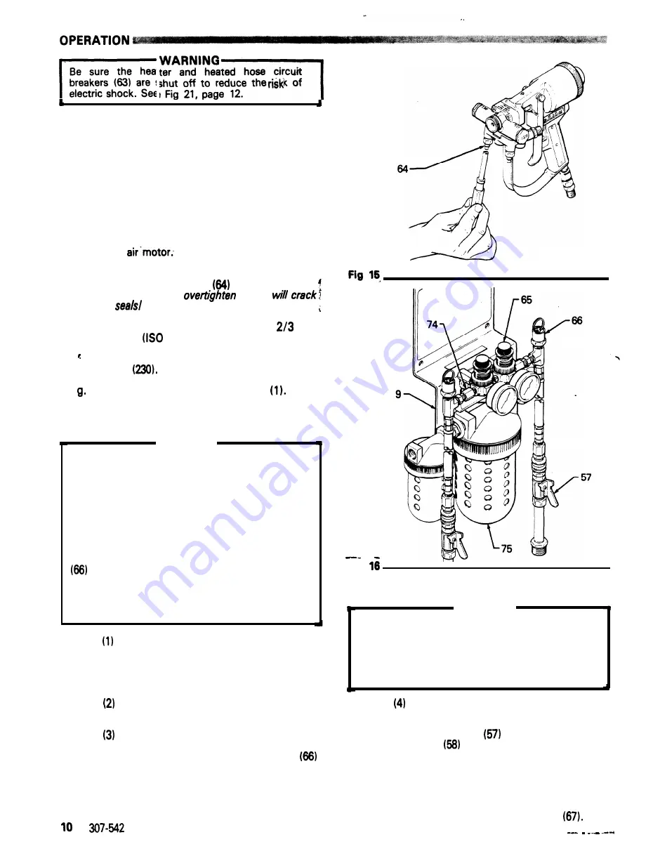
Adjust the Air Dryer (9). See Fig 16.
WARNING
To reduce the risk of overpressurizing the supply
drum or container, which could rupture the drum
and cause serious bodily injury and property
damage, DO NOT operate the Air Dryer with any
part removed.
Do not operate with the restrictor nipple (74)
removed. These nipples limit the volume of air to
the Air Dryer.
Do not operate with either pressure relief valve
removed. These valves relieve air pressure to
the drums if it exceeds 5.5 psi (0.38 bar).
Do not operate with the metal bowl guard (75)
removed from the oil filter or desiccant dryer.
Set both air regulators (65) to the lowest
pressure needed to provide adequate dry
air to the supply drums. A setting of 2 psi
(0.14 bar) normally provides enough dry
air to the drums.
Open the drum shutoff valves (57). Refer to
the Typical Installation.
To lower the pressure on the gauge, turn
the regulator knob counterclockwise and
pull up on the pressure relief valve ring
until the pressure on the gauge is just
below the desired setpoint. Release the
ring then turn the knob to the desired
pressure. See Fig 16.
Fig
I
WARNING
If either pressure relief valve (66) is not operating
properly, or if the drum pressure ever exceeds
5.5 psi (0.38 bar), replace the valve immediately.
A malfunctioning relief valve can allow the drum
to overpressurize and rupture resulting in bodily
injury and
property
damage. Therefore,
never
at-
tempt to repair the valve.
Check the pressure relief valves daily.
To check the relief valves; close the drum
shutoff valves
and uncouple the air
hoses
from the pin fitting.
Increase the air pressure slowly. If pressure
is not relieved by 5.5 psi (0.38 bar),
replace the valve.
NOTE:
A minimum pressure of 1 psi (0.07 bar) is
needed to open the check valves
Summary of Contents for 226-991
Page 1: ...Parts...
Page 16: ...NOTES...
Page 20: ......
Page 21: ......
Page 22: ......
Page 23: ......


