background image

19

IO-242

     5/04

C

OUNTERFLOW

 I

NSTALLATIONS

When the gas piping enters through the left side of the furnace, the
installer must supply a straight pipe to reach the exterior of the
furnace.

A ground joint union, drip leg, and manual shutoff valve must also
be supplied by the installer. In some cases, the installer may also
need to supply a transition piece from 1/2" to another pipe size.
When the gas piping enters through the right side of the furnace,
the installer must supply the following fittings (starting at the gas
valve):

• 90 degree elbow.
• Close nipple.
• 90 degree elbow.
• Straight pipe to reach exterior of furnace.

G

AS

 P

IPING

 C

HECKS

Before placing unit in operation, leak test the unit and gas
connections.

WARNING

T

O AVOID THE POSSIBILITY OF EXPLOSION OR FIRE, NEVER USE A MATCH OR

OPEN FLAME TO TEST FOR LEAKS.

Check for leaks using an approved chloride-free soap and water
solution, an electronic combustible gas detector, or other approved
testing methods.

CAUTION

T

O PREVENT PROPERTY DAMAGE OR PERSONAL INJURY DUE TO FIRE, THE

FOLLOWING INSTRUCTIONS MUST BE PERFORMED REGARDING GAS

CONNECTIONS, PRESSURE TESTING, LOCATION OF SHUTOFF VALVE AND
INSTALLATION OF GAS PIPING.

NOTE:

  Never exceed specified pressures for testing.  Higher

pressure may damage the gas valve and cause subsequent
overfiring, resulting in heat exchanger failure.

Disconnect this unit and shutoff valve from the gas supply piping
system before pressure testing the supply piping system with
pressures in excess of 1/2 psig (3.48 kPa).

This unit must be isolated from the gas supply system by closing
its manual shutoff valve before pressure testing of gas supply piping
system with test pressures equal to or less than 1/2 psig (3.48
kPa).

P

ROPANE

 G

AS

 T

ANKS


AND

 P

IPING

WARNING

I

F THE GAS FURNACE IS INSTALLED  IN A  BASEMENT, AN EXCAVATED

AREA OR A CONFINED  SPACE,  IT IS STRONGLY RECOMMENDED TO
CONTACT A PROPANE SUPPLIER  TO  INSTALL  A GAS DETECTING

WARNING DEVICE IN  CASE OF  A GAS LEAK. 

• 

S

INCE PROPANE GAS IS  HEAVIER THAN  AIR, ANY LEAKING GAS  CAN

  SETTLE IN ANY  LOW  AREAS OR CONFINED SPACES. 

• 

P

ROPANE GAS ODORANT MAY FADE,  MAKING  THE GAS UNDETECTABLE

  EXCEPT  WITH A W ARNING  DEVICE.

A gas detecting warning system is the only reliable way to detect a
propane gas leak. Rust can reduce the level of odorant in propane
gas.  Do not rely on your sense of smell.  Contact a local propane

gas supplier about installing a gas detecting warning system.  If
the presence of gas is suspected, follow the instructions on Page
4 of this manual.

All propane gas equipment must conform to the safety standards
of the National Board of Fire Underwriters, NBFU Manual 58.

For satisfactory operation, propane gas pressure must be 11 inch
WC at the furnace manifold with all gas appliances in operation.
Maintaining proper gas pressure depends on three main factors:

1. Vaporization rate, depending on temperature of the liquid,

and “wetted surface” area of the container or containers.

2. Proper pressure regulation. (Two-stage regulation is

recommended for both cost and efficiency).

3. Pressure drop in lines between regulators, and between

second stage regulator and the appliance. Pipe size will
depend on length of pipe run and total load of all appliances.

Complete information regarding tank sizing for vaporization,
recommended regulator settings, and pipe sizing is available from
most regulator manufacturers and propane gas suppliers.

Since propane gas will quickly dissolve white lead and most
standard commercial compounds, special pipe dope must be used.
Shellac-based compounds resistant to the actions of liquefied
petroleum gases such as Gasolac

®

, Stalactic

®

, Clyde’s

®

 or John

Crane

®

 are satisfactory.

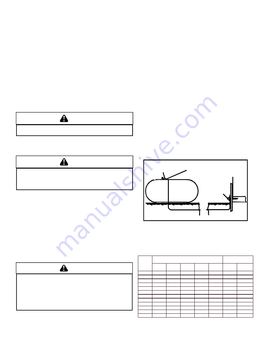
Refer to the following illustration for typical propane gas installations
and piping.

200 PSIG
Maximum

5 to 15 PSIG
(20 PSIG Max.)

Continuous

11" W.C.

Second Stage
Regulator

First Stage
Regulator

 Propane Gas Installation (Typ.)

P

ROPANE

 G

AS

 P

IPING

 C

HARTS

Sizing Between First and Second Stage Regulator*
Maximum Propane Capacities listed are based on 2 psig pressure drop at 10 psig setting.  
Capacities in 1,000 BTU/hour.

Pipe or

Nominal Pipe Size

Tubing

Tubing Size, O.D. Type L

Schedule 40

Length,

3/8"

1/2"

5/8"

3/4"

7/8"

1/2"

3/4"

Feet

10

730

1,700

3,200

5,300

8,300

3,200

7,500

20

500

1,100

2,200

3,700

5,800

2,200

4,200

30

400

920

2,000

2,900

4,700

1,800

4,000

40

370

850

1,700

2,700

4,100

1,600

3,700

50

330

770

1,500

2,400

3,700

1,500

3,400

60

300

700

1,300

2,200

3,300

1,300

3,100

80

260

610

1,200

1,900

2,900

1,200

2,600

100

220

540

1,000

1,700

2,600

1,000

2,300

125

200

490

900

1,400

2,300

900

2,100

150

190

430

830

1,300

2,100

830

1,900

175

170

400

780

1,200

1,900

770

1,700

200

160

380

730

1,100

1,800

720

1,500

To convert to capacities at 15 psig settings - multiply by 1.130
To convert to capacities at 5 psig settings - multiply by 0.879

Summary of Contents for GDS8

Page 1: ...en the unit is in operation Remember it is your responsibility to install the product safely and to know it well enough to be able to instruct a customer in its safe use Safety is a matter of common s...

Page 2: ...ETE THE INSTALLATION 13 FIX 1 LINER TERMINATION 13 FIX 2 CHANGE VENTING ARRANGEMENTS 13 FIX 3 REBUILD THE CROWN 13 FIX 4 RELINING 13 VIII Electrical Connections 14 WIRING HARNESS 14 115 VOLT LINE CONN...

Page 3: ...5 FILTER MAINTENANCE 25 FILTER REMOVAL 26 UPRIGHT FILTER REMOVAL 26 INDUCED DRAFT AND CIRCULATOR BLOWER MOTORS 26 FLAME SENSOR QUALIFIED SERVICER ONLY 26 IGNITER QUALIFIED SERVICER ONLY 26 BURNERS 26...

Page 4: ...ponent failures could result in heating system operational problems TO THE INSTALLER Before installing this unit please read this manual thoroughly to familiarize yourself with specific items which mu...

Page 5: ...ring grounding will be discharged 3 Service integrated control module or connecting wiring following the discharge process in step 2 Use caution not to recharge your body with static electricity i e d...

Page 6: ...lking compound or cement grout Counterflow Installation over a combustible floor If installation over a combustible floor becomes necessary use an accessory subbase see Product Data Book applicable to...

Page 7: ...HE FURNACE POSITION AS CLOSE AS POSSIBLE TO BLOWER DECK TO ALLOW FOR CIRCULATOR BLOWER REMVOAL HOLD DOWN NUTS SUPPORT NUTS 2 x2 x3 8 ANGLE IRON 3 PLACES Suspended Furnace EXISTING FURNACE REMOVAL NOTE...

Page 8: ...furnished with doors are considered a part of the unconfined space 5 3 3 Equipment Located in Confined Spaces a All Air from Inside the Building The confined space shall be provided with two permanen...

Page 9: ...rtical ducts each opening shall have a minimum free area of 1 square inch per 4 000 BTU per hour of total input rating of all equipment in the enclosure Furnace Water Heater Outlet Air Chimney or Gas...

Page 10: ...ada the furnaces must be vented in accordance with the National Standard of Canada CAN CSA B149 1 and CAN CSA B149 2 latest editions and amendments NOTE The vertical height of the Category I venting s...

Page 11: ...OD EQUIPPED APPLIANCE THE POTENTIAL FOR CONDENSATIO N DAM AG E MAY STILL EXIST WITH EXTREMELY COLD CONDITIO NS LONG VENT CONNECTORS EXTERIOR CHIM NEYS OR ANY CO MBINATION OF THESE CONDITIONS THE RISK...

Page 12: ...CHECK 5 LINER CONDITION If a metal liner is present it must be checked It cannot be assumed that all existing metal liners are correctly installed and in good condition Remove the lowest existing vent...

Page 13: ...CSA B149 2 latest editions and amendments assume interior chimneys If in the judgment of the local gas utility installer and or local codes one or more of the above factors is likely to present a prob...

Page 14: ...requirements If a flexible liner is to be used it must be made of the proper materials For most residential applications an aluminum liner should be acceptable If the combustion air supplied to the fu...

Page 15: ...rminal strip as shown in Figure 12 IMPORTANT NOTE To avoid possible equipment malfunction route the low voltage wires to avoid interference with filter removal or other maintenance Integrated Ignition...

Page 16: ...minals TWINNING A twin terminal located on the thermostat terminal strip can be used to twin two furnaces This twin terminal synchronizes the circulation blowers of the two furnaces Furnaces must be s...

Page 17: ...The actual firing rate of the furnace is Input 1 000 heating value of the gas X 3600 constant 52 6 meter time for 1 ft3 of gas Input 3 600 000 52 6 Input 68 400 Btu h METER TIME IN MINUTES AND SECONDS...

Page 18: ...minimum of three inches long Install a 1 8 NPT pipe plug fitting accessible for test gage connection immediately upstream of the gas supply connection to the furnace Use two pipe wrenches when making...

Page 19: ...ely on your sense of smell Contact a local propane gas supplier about installing a gas detecting warning system If the presence of gas is suspected follow the instructions on Page 4 of this manual All...

Page 20: ...is installed and shall be of such a size that the heat exchanger can be viewed for visual light inspection or such that a sampling probe can be inserted into the airstream The access panel must be ma...

Page 21: ...ubleshooting Chart for further explanation of the lighting codes Follow the start up and adjustment items refer to further information in Section XIII Operational Checks FURNACE OPERATION Purge gas li...

Page 22: ...e the number of seconds per cubic foot sec ft3 of gas being delivered to the furnace If the dial is a one cubic foot dial divide the number of seconds recorded in step 2 by one If the dial is a two cu...

Page 23: ...ng ends During normal heating operation the circulator fan will come on approximately 37 seconds after the gas valve opens ON OFF ON OFF ON OFF ON OFF 1 2 1 2 1 2 1 2 90 SECON D DELAY 120 SECON D DELA...

Page 24: ...valve to close and extinguish flame The induced draft blower to be de energized after a fifteen second postpurge and The circulator blower to remain energized continuously until limit control resets 3...

Page 25: ...he red LED If the furnace is in lockout it will or can be reset in any of the following ways 1 Automatic reset The integrated control module will automatically reset itself and attempt to resume norma...

Page 26: ...cleaned by a qualified servicer using emery cloth or steel wool Following cleaning the flame sense signal should be as indicated in the Specifications Sheet IGNITER QUALIFIED SERVICER ONLY If the igni...

Page 27: ...SHES Induced draft blower pressure switch contacts sticking Shorts in pressure switch circuit Inspect pressure switch hose Repair if necessary Inspect flue for blockage proper length elbows and termin...

Page 28: ...er if necessary Check burners for proper alignment Check flue and air inlet piping for blockage proper length elbows and termination Correct as necessary Check induced draft blower for proper performa...

Page 29: ...IR CLEANER ELECTRONIC BLWR CIRCULATOR BLWR ID HUMIDIFIER FLAME SENSOR 115 VAC TRANSFORMER 40 VA 24 VAC C2 GND VALVE GAS CONTROL LIMIT PRIMARY AUTO RESET LIMIT CONTROL S MANUAL RESET ROLLOUT RO1 5 RO2...

Page 30: ...of product failure They are simple to service and forgiving to operate We use quality materials and components Finally every unit is run tested before it leaves the factory That s why we know There s...

Reviews: