3
IO-230F
08/04
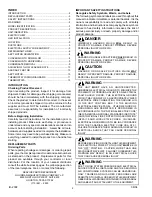
WARNING
THIS PRODUCT IS FACTORY SHIPPED FOR USE WITH
A 208-230/1/60 ELECTRICAL POWER SUPPLY. THIS AIR
HANDLER
MUST NOT
BE RECONFIGURED TO OPERATE
WITH ANY OTHER POWER SUPPLY.
WARNING
WHEN INSTALLING OR SERVICING THIS EQUIPMENT,
SAFETY CLOTHING, INCLUDING HAND AND EYE
PROTECTION, IS STRONGLY ADVISED. IF INSTALLING
THIS EQUIPMENT IN AN AREA THAT HAS SPECIAL
SAFETY REQUIREMENTS (HARD HATS ETC.), OBSERVE
THESE REQUIREMENTS. TO PROTECT THE UNIT WHEN
WELDING CLOSE TO THE PAINTED SURFACES, THE
USE OF A QUENCHING CLOTH IS STRONGLY ADVISED
TO PREVENT SCORCHING OR MARRING OF THE
EQUIPMENT FINISH.
WARNING
THE UNITED STATES ENVIRONMENTAL PROTECTION
AGENCY (“EPA”) HAS ISSUED VARIOUS REGULATIONS
REGARDING THE INTRODUCTION AND DISPOSAL OF
REFRIGERANTS INTRODUCED INTO THIS UNIT.
FAILURE TO FOLLOW THESE REGULATIONS MAY HARM
THE ENVIRONMENT AND CAN LEAD TO THE
IMPOSITION OF SUBSTANTIAL FINES. THESE
REGULATIONS MAY VARY DUE TO THE PASSAGE OF
LAWS. A CERTIFIED TECHNICIAN MUST PERFORM THE
INSTALLATION AND SERVICE OF THIS PRODUCT.
SHOULD QUESTIONS ARISE, CONTACT YOUR LOCAL
EPA OFFICE.
CARBON MONOXIDE POISONING HAZARD
-
Special Warning for Installation of Furnace or Air Handling Units in
Enclosed Areas such as Garages, Utility Rooms or Parking Areas
Carbon monoxide producing devices (such as an automobile, space
heater, gas water heater, etc.) should not be operated in enclosed areas
such as unventilated garages, utility rooms or parking areas because of
the danger of carbon monoxide (CO) poisoning resulting from the exhaust
emissions. If a furnace or air handler is installed in an enclosed area such
as a garage, utility room or parking area and a carbon monoxide producing
device is operated therein, there must be adequate, direct outside
ventilation.
This ventilation is necessary to avoid the danger of CO poisoning which
can occur if a carbon monoxide producing device continues to operate in
the enclosed area. Carbon monoxide emissions can be (re)circulated
throughout the structure if the furnace or air handler is operating in any
mode.
CO can cause serious illness including permanent brain damage or death.
B10259-216
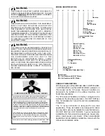
MODEL IDENTIFICATION
Model Series
AE = Air Handler with ECM™ Motor
AR = Air Handler with PSC Motor
Cabinet Finish
P = Painted
U = Unpainted Galvanized Steel
Refrigerant Metering
T = TXV
F = Flowrater
Normal Capacity
018 = 1½ Ton
024 = 2 Ton
030-032 = 2½ Ton
036 = 3 Ton
042 = 3½ Ton
048 & 049 = 4 Ton
060 & 061 = 5 Ton
Factory Installed Heat
00 = None
Feature
A = Initial Release
B = Downflow
C = Factory Sealed
Electrical
Supply
208 - 230/1/60
AR
U
F
024
00
A
1
A
Revision
PRODUCT DESCRIPTION
With the exception of the ARPF024-00B-1, ARPF036-00B-
1, ARPF048-00B-1 and the ARPF060-00B-1 (refered to in
this manual as the “B” series), these air handlers are
designed to be installed in the upflow, downflow, and
horizontal orientations.
The “B” series air handlers are factory configured to be
installed in the downflow orientation. DO NOT INSTALL
THE “B” SERIES IN THE UPFLOW OR HORIZONTAL
POSITION.
The “C” series airhandler is designed for low leak
applications. These air handlers are designed for indoor
use only and must only be installed in a weatherized area.
DO NOT INSTALL OUTDOORS. Typical residential
installations for this product include alcoves, basements,
attics, crawl spaces, and closets. Other nonresidential
applications are acceptable provided they comply with this
manual and local/state codes.


