Goodman AEPT Installation And Operating Instructions Manual Download Page 13

13

IO-230F

08/04

Quality Makes the Difference!

All of our systems are designed and manufactured with the same high quality standards
regardless of size or efficiency. We have designed these units to significantly reduce the
most frequent causes of product failure. They are simple to service and forgiving to operate.
We use quality materials and components. Finally, every unit is run tested before it leaves
the factory. That’s why we know. . . 

There’s No Better Quality.

Visit our websites at 

www.goodmanmfg.com

 or 

www.amana-hac.com 

for information on:

Products

Warranties

Customer Services

Parts

Contractor Programs and Training

Financing Options

© 2003-2004 Goodman Manufacturing Company, L.P.
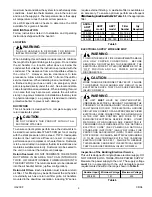
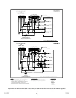
THERMOSTATS

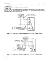
Note: Second Stage heat can be accomplished by multi-
stage heating thermostat or the addition of an outdoor
thermostat as shown in Figures 12 and 13.

Goodman part number CHT18-60 is a single-stage cool
and single-stage heat thermostat.

Goodman part number HPT18-60 is a single-stage cool,
two-stage heat pump thermostat. The first stage is heat
pump heating and the second stage is optional electric heat.

If additional features are desired, such as digital or
programmable capabilities, these thermostats are
commercially available. Follow the thermostat
manufacturer’s instruction for installation.

START-UP PROCEDURE

Prior to start-up, ensure that all electrical connections
are properly sized and tightened.

All panels must be in place and secured. For Air Tight
application, neoprene gasket must be positioned at
prescribed locations to achieve 2% leakage.

Tubing must be leak free.

Unit should be elevated, trapped and pitched to allow
for drainage.

Low voltage wiring is connected.

Auxiliary drain is installed when necessary and pitched
to allow for drainage.

Drain pan and drain tubing has been leak checked.

Return and supply ducts are sealed.

Unit is elevated when installed in a garage or where
flammable vapors may be present.

Unit is protected from vehicular or other physical
damage.

Return air is not  obtained from any areas where there
may be objectionable odors, flammable vapors or
products of combustion such as carbon monoxide
(CO), which may cause serious personal injury or
death.

REGULAR MAINTENANCE

WARNING

DISCONNECT  ALL POWER SUPPLIES BEFORE
PERFORMING ANY SERVICE.  NOTE THAT THERE MAY
BE MORE  THAN ONE POWER SUPPLY.  FAILURE  TO
OBSERVE THIS WARNING CAN RESULT IN ELECTRICAL
SHOCK  THAT CAN CAUSE PERSONAL INJURY OR
DEATH.

The only item to be maintained on a regular basis by the
user is the circulating air filter(s).  Filter should be cleaned
or replaced regularly.  A certified service technician must
perform all other services.

Summary of Contents for AEPT

Page 1: ...Company L P IO 230F 2550 North Loop West Suite 400 Houston Texas 77092 08 04 www goodmanmfg com or www amana hac com 2003 2004 Goodman Manufacturing Company L P INSTALLATION OPERATING INSTRUCTIONS FO...

Page 2: ...092 713 861 2500 IMPORTANT SAFETY INSTRUCTIONS Recognize Safety Symbols Words and Labels The following symbols and labels are used throughout this manual to indicate immediate or potential hazards It...

Page 3: ...area such as a garage utility room or parking area and a carbon monoxide producing device is operated therein there must be adequate direct outside ventilation This ventilation is necessary to avoid t...

Page 4: ...USTAGREE UNLESS USING HKR3 3 PHASE SERIES HEAT KIT THIS AIR HANDLER DOES NOT HAVE FACTORY INSTALLED ELECTRIC HEAT ELECTRIC HEAT ISAVAILABLE AS AN ACCESSORY IF INSTALLING THIS OPTION THE ONLY HEAT KITS...

Page 5: ...OR OBJECTIONABLE FUMES ODORS INTO THE DUCTWORK The return ductwork is to be introduced into the air handler bottom upflow configuration Return Air Filters Each installation must include a return air f...

Page 6: ...e building supply connects to the stripped black and white wires contained in the air handler electrical compartment cavity Aground screw is also contained in this area Attach the supply wires to the...

Page 7: ...NT NOTE In order to prevent damage to the sensing bulb it is not permanently installed in the factory This bulb is to be removed prior to brazing Place in proper location after braze joint has cooled...

Page 8: ...that allows for access to all sides To prevent the evaporator coil pan from sweating the DPI accessory insulation kit is to be used when performing this conversion Note The DPI kit is not supplied wi...

Page 9: ...te The upper drain will become the secondary drain which is mandatory in many municipalities 7 Install the plastic plug removed in step 5 to the right side lower access panel and the oval shaped rubbe...

Page 10: ...n the OFF position For most applications this setting is to be changed according to the electric heat size and the outdoor unit selection The AEPT product uses a General Electric ECMTM motor This moto...

Page 11: ...PT MODELS SEE SUPPLEMENTAL INSTALLATION AND OPERATING INSTRUCTIONS FOR AEPT MODELS ROOM THERMOSTAT W Y G R 18 GA 4 WIRES WITH COOLING 3 WIRES WITHOUT R G W Y TO CONDENSING UNIT 24V CONNECTIONS 18 GA 2...

Page 12: ...UF ARPF ARPT 18 60 ABOVE 10 KW HEAT PUMP B L U E W H I T E C W2 R E D Y O R R Y C O W2 18 GA 7 WIRE R G E R AR UNIT RED OT 1 OT 2 3 EHR 1 2 4 BROWN SEE NOTE 2 NOTES 1 OUTDOOR THERMOSTAT OT 1 SHOULD BE...

Page 13: ...y available Follow the thermostat manufacturer s instruction for installation START UP PROCEDURE Prior to start up ensure that all electrical connections are properly sized and tightened All panels mu...

Reviews: