11
IO-230F
08/04
Humidity Control
When using a Humidistat (normally closed), cut jumper PJ6 on the control board. The Humidistat will only affect cooling
airflow by adjusting the Airflow to 85%.
Two Stage Heating
When using staged electric heat, cut jumper PJ4 on the control board.
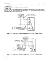
Thermostat Wiring
Use
thermostat wiring diagram
Figures 10 thru 13
and those provided with the thermostat when making these connections.
NOTE: DO NOT USE THESE DIAGRAMS FOR AEPT MODELS. SEE SUPPLEMENTAL INSTALLATION AND
OPERATING INSTRUCTIONS FOR AEPT MODELS.
ROOM THERMOSTAT
W
Y
G
R
#18 GA. 4 WIRES WITH
COOLING 3 WIRES WITHOUT
R
G
W
Y
TO CONDENSING
UNIT 24V. CONNECTIONS
#18 GA. 2 WIRES
BLUE
WHITE
GREEN
RED
CONTACTOR
COIL
AR UNIT
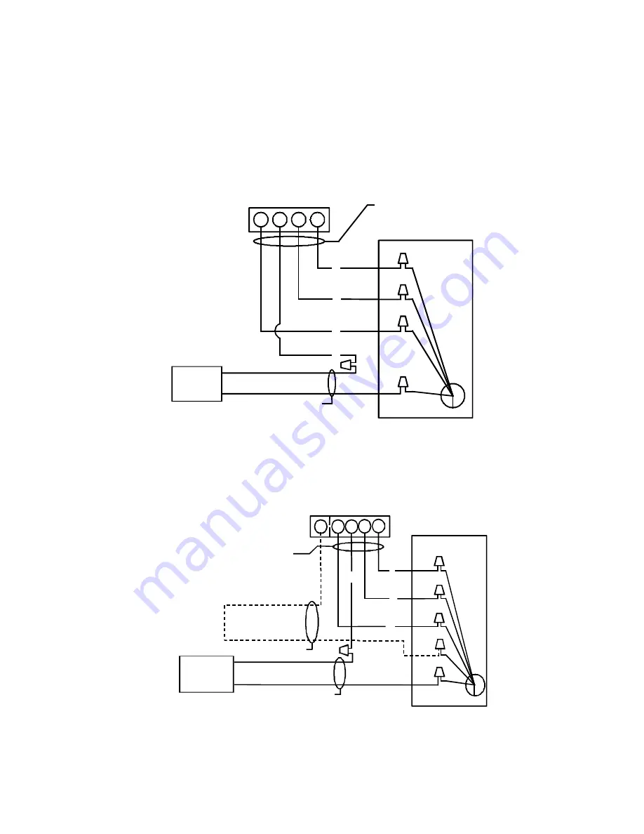
Figure 10 - Low Voltage Wiring Diagram for Cooling Unit with optional heat kit 10KW and below
W2
W Y G R
R
G
Y
W
GREEN
RED
WHITE
BLUE
BROWN
#18 GA. 4 WIRE WITH
COOLING 3 WIRE WITHOUT
ROOM THERMOSTAT
OUTDOOR
THERMOSTAT
(OPTIONAL)
CONDENSING
UNIT 24V. CONNECTIONS
#18 GA. 2 WIRES
#18 GA. 2 WIRES
CONTACTOR
COIL
AR UNIT
Figure 11 - Low Voltage Wiring Diagram for Cooling Unit with optional heat kit 15KW and above


