


RUDDER CONTROL INSTALLATION
1. The CORVUS is supplied with a high quality set of pull-pull cables and
ball-links. NOTE: There are pictures of other planes in this manual,
however, the SBACH is assembled the same way.
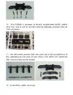
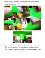
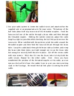
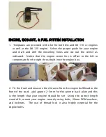
2. Install your rudder servo(s) into the precut locations in the fuselage.
You will need 3 inch arms on the servo(s). Or you can mount the
supplied rudder arm to your circular servo arm. If you use two rudder
servos it is best to connect them to two separate channels and mix them
together in your radio. Set up your radio accordingly and center the
rudder servo(s). The geometry of your servo arms relative to each other
and the rudder horn is critical for proper rudder operation without
binding or excess cable slack.
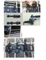
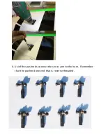
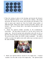
3. If you are using two rudder servos you will need to set up the servo
coupling very accurately to assure zero binding and drain on your
batteries. Threaded couplers and ball links are provided for your use. If
you are new to multiple servos ganging and programming of servos,
highly recommends you seek the assistance of an experienced modeler
in your area. Miss programming of servos can lead to very high drain on
your batteries and possible servo failures.
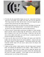
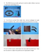
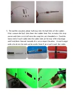
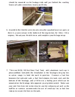
4. Locate the pull-pull cable set, threaded couplers, brass swaging tubes,
and ball-links. If the cable is one long piece, cut it into two equal length
pieces. Thread one end of the one cable through a brass tube and then
through one of the threaded couplers. Run the cable back through the
brass tube and then loop it back through a second time. Using a set of
crimping pliers, place three crimps just tight enough not to cut the brass
tube but enough to securely hold the wire in place. Cut off the excess
cable with wire cutters. Wick thin CA into the brass tube to help hold
the cable secure. Repeat for the other cable.
Summary of Contents for Corvus Racer 540 120CC
Page 1: ...GoldWing RC Corvus Racer 540 120CC Giant Scale Aerobatic Aircraft...
Page 10: ...Carbon Fiber accessories version Extra strength carbon fiber control horns...
Page 13: ...Scheme A White yellow black Scheme B Red white black...
Page 14: ...Scheme C White red black...
Page 21: ......
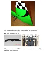
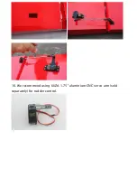
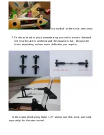
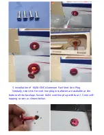
Page 23: ...16 We recommend using KUZA 1 75 aluminium CNC servo arm sold separately for rudder control...
Page 27: ......
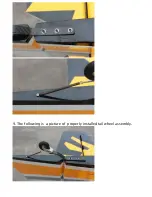
Page 30: ...9 The following is a picture of properly installed tail wheel assembly...
Page 60: ...GoldWing RC www goldwingrc com...


