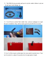


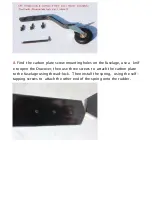
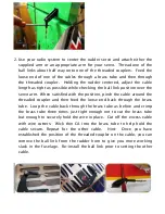

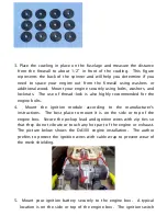
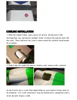
2. Use your radio system to center the rudder servo and attach either the
supplied arm or an appropriate arm for your servo. Thread one of the
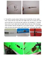
ball links about half way onto one of the threaded couplers. Feed the
loose end of one of the cables through a brass tube and then through
the threaded coupler. Holding the rudder centered, adjust the cable
length as tight as possible while checking the ball link position over the
servo arm. When satisfied with the position, pinch the cable around the
threaded coupler and then feed the loose end back through the brass
tube. Loop the cable back through the brass tube as before and crimp
the brass tube three times just tight enough not to cut the brass tube
but enough to securely hold the wire in place. Cut off the excess cable
with wire cutters. Wick thin CA into the brass tube to help hold the
cable secure. Repeat for the other cable.
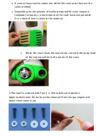
Hint:
Once you have
established the position of the threaded coupler on the cable, you can
remove the ball link from the rudder horn to give you more working
slack in the fuselage. Re-install the ball link prior to setting the other
cable.
Summary of Contents for Corvus Racer 540 120CC
Page 1: ...GoldWing RC Corvus Racer 540 120CC Giant Scale Aerobatic Aircraft...
Page 10: ...Carbon Fiber accessories version Extra strength carbon fiber control horns...
Page 13: ...Scheme A White yellow black Scheme B Red white black...
Page 14: ...Scheme C White red black...
Page 21: ......
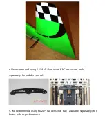
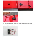
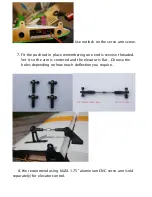
Page 23: ...16 We recommend using KUZA 1 75 aluminium CNC servo arm sold separately for rudder control...
Page 27: ......
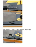
Page 30: ...9 The following is a picture of properly installed tail wheel assembly...
Page 60: ...GoldWing RC www goldwingrc com...


