background image

17

REPAIRS

Replacing / repairing the retention valve(s)

Replacing / repairing the safety valve 

01

01

02

02

03

03

Used tools: 

- Fixed Key 11/16”
- Fixed Key 1/2”
- Fixed Key 25/32”
- Activator Loctite 7471
- Tread lock “Loctite 242”

- Disconnect of the retention valve the hose with steel mesh originating from the 

motor head (01);

- Loosen the screw that arrests the air plastic hose (02);

- Loosen the tank retention valve (03).

- Remove the ring fixed in the valve stem (01);

- Remove the plastic sleeve of the valve finishing (02);

- Loosen the safety valve of the pressostat set (03).

- Dismount the valve (A) and verify if the same is damaged. 

If yes, change it, if not, make its cleaning.

IMPORTANT: 

After the repair /substitution procedure of 

the components, mounting them again, it is of extreme 

importance that it is guaranteed the points complete sealing, 

using activator and lock thread glue

.

A

Summary of Contents for BioQualyAir 40L

Page 1: ......

Page 2: ...ão Preto S P Brasil Fone 55 16 2102 5000 Fax 55 16 2102 5001 C N P J 48 015 119 0001 64 Insc Est 582 329 957 115 www gnatus com br gnatus gnatus com br Technical Duties Gilberto Henrique Canesin Nomelini CREA SP 0600891412 OPERATING INSTRUCTIONS ATTENTION For greater safety Read and understand all the directions contained in this Manual before installing or operating this equipment Note This Manua...

Page 3: ...NS RESTRICTIONS AND WARNINGS 13 Transportation storage and operation 13 Precautions and warnings during the use of equipment 14 Precautions and warnings after the use of equipment 14 Precautions and warnings during the cleaning of equipment 14 Sensitivity to environmental conditions in normal situations of use 15 Precautions to be adopted against foreseeable or uncommon risks related to the deacti...

Page 4: ...om overheating Models with tanks of 38 and 65 liters both with internal antioxidant painting ensuring greater durability of the compressor IDENTIFICATION OF THE EQUIPMENT Description of Equipment Principles and fundamentals applied to the product operation All components of the equipment are mounted over the air tank One or more electric engines trigger the pistons system with rings made of non me...

Page 5: ...D MATERIALS OF CONSUMPTION Detai A Box of electric command Rear view BioQualyAir 40L BioQualyAir 65L Characteristics and operation A A 02 03 01 01 15 14 17 18 16 04 04 11 10 09 09 08 08 07 07 06 12 13 06 05 5a 5a 05 13 12 03 11 10 02 ...

Page 6: ...c function is to protect the integrity of the compressor against overpressure or underpressure applied to the same during your operation 5a On Off Key Located at the top of pressostat it serves to connect or disconnect the compressor 06 Air reservoir Local where the compressed air is deposited 07 Air reservoir manometer It indicates the pressure value inside the air reservoir 08 Safety valve press...

Page 7: ...ects automatically the valve solenoid withdraws compressed air of the head interior thus when going again in operation the motor initiates the process with less effort 16 Bar connector terminal Multiple connectors for electric conductors 17 Overload protector protection relay Its function against overload is to disconnect the equipment mains before that they are reached current and time values tha...

Page 8: ...de 1 14 HP BioQualyAir 65L 127V 2 motores de 1 12 HP BioQualyAir 65L 220V 2 motores de 1 14 HP Weight Gross weight BioQualyAir 40L 45 8 Kg BioQualyAir 65L 71 2 Kg Net weight BioQualyAir 40L 30 6 Kg BioQualyAir 65L 50 4 Kg TECHNICAL SPECIFICATIONS Other specifications Capacity of dental sets BioQualyAir 40L 1 dental sets BioQualyAir 65L 2 dental sets Air Tank capacity BioQualyAir 40L 38 liters BioQ...

Page 9: ...9 TECHNICAL SPECIFICATIONS Dimensions mm BioQualyAir 65L BioQualyAir 40L ...

Page 10: ...nt must be stored or transported with light shield It determines the temperature limits within the packaging must be stored or transported Careful I t indi cates an important instruction for the operation of the product Not following it can cause dangerous malfunctioning Note It indicates useful information for operation of the product Important It indicates an instruction of safety for operation ...

Page 11: ... an environment where vapors anesthetic mixtures infl ammable with air or oxygen and nitrous oxide can be detected Check the voltage of the equipment at the moment of executing the electrical installation Electricinstallation Breaker dimensioning Wire gauge dimensioning BioQualyAir 40L BioQualyAir 65L Wire diameter Gauge For the distance up to 5m of breaker until the outlet of the equipment the wi...

Page 12: ...er installation Connect the air filter in the motor head Pass the lock thread Loctite 242 on the filter screw and fix it using one fix key type of 5 8 Fig A and B Never activate the compressor without the aspiration filter the entrance of strange bodies or of dust can provoke serious damages in the internal components OPERATION OF EQUIPMENT Powering the BioQualyAir up Turn the power switch 05a to ...

Page 13: ...ing on the pressure gauge 09 The air outflow rate can also be adjusted in the register 10 In tandem with the pressure and flow rate registers there is a filter that removes moisture and impurities remaining in the air the moisture that is removed from the outlet will get stored in the reservoir A to empty it press the pin underneath the reservoir 11 09 A 10 12 12 PRECAUTIONS RESTRICTIONS AND WARNI...

Page 14: ...ompressor is turned off those parts still remain hot for some time so avoid contact Make sure periodically that the air inlet and outlet are not obstructed If there is power outage it is recommended to turn off the compressor power switch to prevent the disarming of the thermal relay when power returns again Before disconnecting the pressure hose from the compressor for any reason first close the ...

Page 15: ...TIVE AND PREVENTIVE MAINTENANCE AND PRESERVATION The equipment should be calibrated routinely as per the legislation in force in the country But never with a period exceeding 3 years Preventive Maintenance FIlter Change Keep the air filter s B clean and in good condition of usage The air filter B prevents dust from entering into the compressor and reduces the operating noise Over time the filter w...

Page 16: ...ressor Fixed key type 14mm Fixed key type 1 2 Fixed key type 5 8 Key type Allen 14mm Fixed key type 11 16 Key type Phillips Fixed key type 10mm Cutting blade style or similar Fixed key type 1 Crimping pliers Fixed key type 25 32 Universal pliers Activator Loctite 7471 Device to verify electric magnitude multimeter test lamp and others Lock thread Loctite 242 17 17 Overload protector The overload p...

Page 17: ...ew that arrests the air plastic hose 02 Loosen the tank retention valve 03 Remove the ring fixed in the valve stem 01 Remove the plastic sleeve of the valve finishing 02 Loosen the safety valve of the pressostat set 03 Dismount the valve A and verify if the same is damaged If yes change it if not make its cleaning IMPORTANT After the repair substitution procedure of the components mounting them ag...

Page 18: ...ter the repair substitution procedure of the components when mounting them again it is of extreme importance that it is guaranteed the points complete sealing using activator and lock thread glue IMPORTANT After the repair substitution procedure of the components when mounting them again it is of extreme importance that it is guaranteed the points complete sealing using activator and lock thread g...

Page 19: ...or 01 Remove the connection box cover fig 01 pag 18 Loosen all the wires of the connection box 01 Solenoid Connection Earth Motor feeding Unscrew the pass cables 02 Loosen the box of electric command removing the four screws 03 After loosening the command box shift it to enable the pressostat removal Remove pressostat and provide the substitution 04 Remove the pressure manometer 01 and provide the ...

Page 20: ...After the repair substitution procedure of the components when mounting them again it is of extreme importance that it is guaranteed the complete points sealing using activator and lock thread glue Used tools Fixed key 7 16 Fixed key 1 Fixed key 11 16 Fixed key 14mm Activator Loctite 7471 Thread lock Loctite 242 Loosen the hose with steel mesh of the motor output head 01 and input of the retention...

Page 21: ...completely 08 09 After loosening the motor shift it to enable the access to the box of electric command interior 10 Loosen the solenoid valve through the four screws and washers 11 Locate the connectors bar remove the protection acrylic sleeve and disconnect the cables of the motor connection 12 06 07 10 11 12 13 14 After loosening the cables of the connector remove it pulling by the command box o...

Page 22: ...or under the command box 19 Remove the overload protector and provide the substitution 20 IMPORTANT After the repair substitution procedure of the components when mounting them again it is of extreme importance that it is guaranteed the complete points sealing using activator and lock thread glue With the valve solenoid already loose from command box fig 11 pag 21 loosen their electric cables and ...

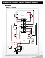
Page 23: ... and 220V 60Hz are of 25 μF or 35 μF Capacitors used in the compressors of 127V 60Hz are of 85 μF After making any maintenance procedure in the components solenoid valve overload protector and capacitor the electric connections should be accomplished as the connection diagram page 24 Used tools Fixed key 14mm Fixed key 10mm Fixed key 1 2 Fixed key 11 16 Phillips key Crimping plier Activator Loctit...

Page 24: ...24 DIAGRAM Connection diagram ...

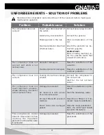
Page 25: ...rical voltage smaller Connect the compressor to the correct net Wait for the net normali zation The compressor does not reach maximum pressure smaller efficiency it works for a short period of time Damaged pressostat Air reservoir is with excess of condensate water Air input filter with excess of residues Motor head with damaged gasket Make the substitution of pres sostat Drain the reservatory wat...

Page 26: ...conformity with the specifications described in the manual Air loss by the solenoid valve with the compressor sto pped Retention valve damaged or with residues interfe ring in its normal operation Unload the air contained in the reservoir remove the re tention valve disassemble it and verify if the valve is da maged If yes change it if no make its cleaning Air loss by the valve sole noid with the c...

Page 27: ...roduct not indicated by the factory F Falls or blows which the equipment may undergo or lack of observation of an compliance with the guidelines of the Owner s Manual which was delivered with the present document together with the equipment Repair or replacement of parts during the warranty period shall not extend the validity term of their warranty This warranty doe snot exempt the customer from ...

Page 28: ......

Reviews: