background image

PA G E   2 6  I n s t r u c t I o n   m A n uA l  

t X 4 5 0 0 s

DC POWEr CONNECTION

the tX4500s is designed for 13.8 V Dc negative 
earth installations only (i.e. where the negative side 
of the battery is connected to the frame or chassis of 
the vehicle). there are two recommended methods of 
installation. Please refer to the following diagrams.

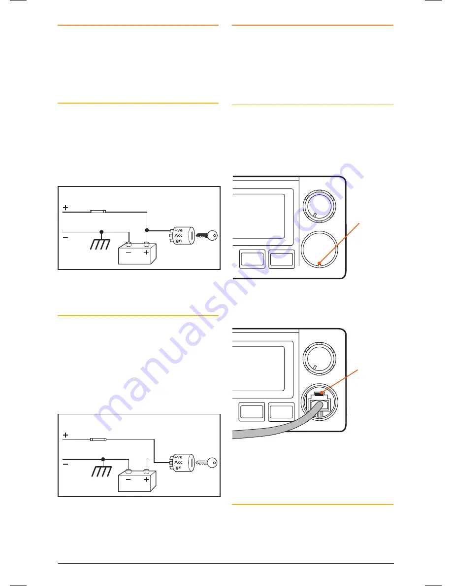
Radio Remains On when the Ignition Switch 
is Off

connect the radio’s negative (Black) lead to the 
vehicle’s chassis or if preferred directly to the 
battery’s negative terminal.
connect the radio’s positive (red) lead, via the 
2 Amp fuse, to the battery’s positive terminal or 
to a point in the fuse box that has +13.8 volts 
continuously available.

Radio remains ON when ignition switch is OFF

RED

Fuse

Fuse

BLACK

Chassis

Car battery

Ingnition Switch 

Radio turns ON and OFF with ignition switch

RED

BLACK

Chassis

Car battery

Ingnition Switch 

To Radio

To Radio

the radio can now be switched on or off at any 
time using the switch on the 

volume

 control.

Radio Turns On and Off with the Ignition Switch

connect the radio’s negative (Black) lead to the  
vehicle’s chassis or if preferred directly to the 
battery’s negative terminal.

connect the radio’s positive (red) lead, via the 2 
amp fuse, to the accessory point in the fuse box. 
this point should 13.8 volts onlY when 
the ignition is switched on or in the AccEssorY 
position.

Radio remains ON when ignition switch is OFF

RED

Fuse

Fuse

BLACK

Chassis

Car battery

Ingnition Switch 

Radio turns ON and OFF with ignition switch

RED

BLACK

Chassis

Car battery

Ingnition Switch 

To Radio

To Radio

the radio should now switch on and oFF 
automatically with the vehicle’s ignition switch. 

MICrOPHONE

the tX4500s is fitted with two microphone sockets 
– one on the front panel and one on the rear. the 
6 pin microphone connector can be plugged into 
either socket. In fact, if the situation requires it, two 
microphones can be connected simultaneously. the 
first microphone keyed takes priority.

Front

the front microphone socket is fitted with a hard 
protective cover. the cover is a press fit. to remove 
the cover, insert a paper clip or similar into the small 
slot in the edge of the cover and lift the cover away 
from the panel. retain the cover in case you require 
it later on.

SILEN T

QUIE T

DUP

ALPH A

VOLUME

lift panel 
here

Position the microphone plug so the plastic tab faces 
upwards then press the plug into the socket until  
it ‘clicks’.

SILEN T

QUIE T

DUP

ALPH A

VOLUME

Plastic tab

Gently press the rubber strain relief grommet 
into the hole surrounding the socket so that the 
slot around the grommet fits neatly inside the lip 
inside the hole.

Rear

If using the rear microphone connection you 
should obtain the optional lEm6P rear microphone 
extension lead. mount the socket on a convenient 
location and feed the plug through the dashboard to 
the DIn cavity.

46885-4_TX4500S_IM.indd   26

4/06/14   3:08 PM

Summary of Contents for TX4500S

Page 1: ...I N S T R U C T I O N M A N U A L ScanSuite faster smarter scanning DIN size fully featured 5 watt UHF CB radio...

Page 2: ...s and Duplex Mode 8 Priority Channels 9 Scanning 10 Open Scan 10 Group Scan 11 Addtional Open Group Scan Options 12 Network Scan Net Scan 12 Using The Priority Channel While Scanning 14 CTCSS DCS 14 S...

Page 3: ...80 The mixing of narrowband and wideband radios in the same spectrum can cause some possible operating issues of interference and varying levels of received volume Possible issues When a new narrowba...

Page 4: ...n reception by fine tuning the receiver frequency to match that of an incoming signal This prevents your Squelch from opening to unwanted interference and ensures incoming signals remain clear and und...

Page 5: ...Display Channel Control Speaker Squelch Control Menu Function Scan OS GS Priority 1 Priority 2 Duplex Alpha Silent Quiet Front Mic Socket LCD PANEL Scan Quiet Busy Transmit Channel Display SelCall Al...

Page 6: ...sent The Squelch can be opened or closed using the Squelch control When the Squelch is open the receiver s background noise can be heard and the symbol is displayed When the Squelch is closed the rece...

Page 7: ...lable settings Rotate the Channel control left or right to adjust the current setting There are three backlight settings available BKLGT Brightness Setting Provides a continuously variable brightness...

Page 8: ...h an earpiece or headphones The Silent Squelch Tail function removes this Squelch Tail reducing it to a faint click as the Squelch closes To Enable or Disable the Silent Squelch Tail 1 Press and hold...

Page 9: ...e for normal direct radio to radio communications To Enable Duplex on a Repeater Channel 1 Select the required repeater channel 1 8 41 48 2 Briefly press the DUP key The duplex symbol will appear on t...

Page 10: ...o exit Auto Skip While scanning if an active channel in your scan group becomes a nuisance by constantly interrupting the scan briefly press the SKIP key on the microphone The radio will temporarily r...

Page 11: ...heard and will remain there for as long as the channel remains busy Once the channel has been clear for 5 seconds scanning will resume automatically If you don t wish to listen to a busy channel brie...

Page 12: ...he microphone to temporarily skip that channel and resume scanning see Auto Skip on page 10 If the radio is paused on a busy channel and you want to remain there briefly press the SCAN key The radio w...

Page 13: ...els To quickly determine which channels are currently programmed into the Net Scan group 1 With the NETWORK scan group selected briefly press the MENU key F will be displayed 2 Rotate the Channel cont...

Page 14: ...signal that is strong enough If the channel is busy with other stations the Squelch will be constantly opening making it difficult to determine which calls are meant for you CTCSS DCS provides selecti...

Page 15: ...e Configuration menu If CTCSS DCS has been set to OFF Silent mode is inhibited To Disable Silent Mode on a Channel 1 Select the required channel An icon CTCSS or icon DCS will be displayed indicating...

Page 16: ...nt nothing will be heard in the speaker You can activate the Quiet Mode on individual channels i e some channels can be set to remain Quiet while others can remain open to all incoming signals USING S...

Page 17: ...emory in locations C0 to C9 3 Briefly press the F then ALPHA to select the ALPHA mode ALPHA will be displayed briefly 4 If the ALPHA label is empty will be displayed otherwise it will display the last...

Page 18: ...for Quiet operation To Remove the QUIET Tag from Individual Channels 1 Select a channel that has been tagged for Quiet operation Q will be displayed 2 Briefly press F then hold QUIET until the radio b...

Page 19: ...the Scan group to 4 or less GROUP CALLING The SelCall system includes a Group call function which allows you to call up to 1000 radios simultaneously This can be useful in an emergency situation wher...

Page 20: ...eceiving a Group call is identical to receiving a normal SelCall except that the alarm sound is a LOW tone beep instead of the normal High tone beep The caller s Ident or ALPHA label appears on the di...

Page 21: ...any frequencies Selecting Frequency Steps Note This menu option is only available when RX only channels are selected The frequency step is the spacing between frequencies when the Channel control is...

Page 22: ...have stored channels into different channel banks you will need to select the appropriate channel bank to access them Note Under normal operation only those channels that have been programmed with fr...

Page 23: ...fly press the Menu key to step through the available menu options Rotate the Channel control to change the selected menu option After viewing or making changes briefly press the PTT to exit the menu o...

Page 24: ...fault 12 5 kHz steps 25 kHz steps Note This option does not affect the standard 80 CB channel spacing Filter Bandwidth only available on CB channels Selects the receiver bandwidth filter on channels 1...

Page 25: ...ed on following pages and the connectors are accessible through the DIn cavity Installing the DIN Bracket 1 remove the four small front mounting screws from the front edges of the DIn mount and separa...

Page 26: ...ed ON or in the ACCESSORY position Radio remains ON when ignition switch is OFF RED Fuse Fuse BLACK Chassis Car battery Ingnition Switch Radio turns ON and OFF with ignition switch RED BLACK Chassis C...

Page 27: ...etection system to warn you if an overvoltage situation occurs If the power supply voltage exceeds 18 volts DC the channel display will flash hi dc for 5 seconds when the unit is first turned on or at...

Page 28: ...DCS CODE DCS CODE DCS CODE DCS CODE DCS CODE 1 023 19 116 37 225 55 325 73 452 91 627 2 025 20 122 38 226 56 331 74 454 92 631 3 026 21 125 39 243 57 332 75 455 93 632 4 031 22 131 40 244 58 343 76 46...

Page 29: ...1875 12 476 700 32 477 200 52 476 7125 72 477 2125 13 476 725 33 477 225 53 476 7375 73 477 2375 14 476 750 34 477 250 54 476 7625 74 477 2625 15 476 775 35 477 275 55 476 7875 75 477 2875 16 476 800...

Page 30: ...ion 70 dBc Frequency Error 1 5 kHz Modulation FM Maximum Deviation 2 5 kHz at 20 dB AF limiting Transmit Frequency Response 6 dB per octave 300 Hz to 3 kHz 1 3 dB Demodulated Audio Signal to Noise 45...

Page 31: ...ing the services supplied again 2 4 For repairs outside the warranty period we warrant our repairs to be free from defects in materials and workmanship for three months from the date of the original r...

Page 32: ...n of Standard Communications Pty Ltd Head Office PO Box 96 Winston Hills NSW 2153 Australia New Zealand PO Box 58 446 Botany Auckland 2163 NZ T 09 274 0955 All other international enquiries email expo...

Page 33: ...Remote PTT and programmable function keys with steering wheel mount I N S T R U C T I O N M A N U A L...

Page 34: ...e is also included for mounting in your vehicle allowing effective hands free communications while driving Once the W1 is connected to your radio several new options will be enabled in your radio s me...

Page 35: ...fit battery cover Close cover fully until it clicks INSTALLATION Range The W1 has a line of sight range of around 5 7 meters depending on the installation Range may be reduced slightly if the radio or...

Page 36: ...mp over and secure the W1 using the two screws provided The clamp has a number of holes and slots to allow the remote control to be rotated and secured at almost any angle Rotate W1 for desired positi...

Page 37: ...lied adhesive foam Mount the W1 in a location that is easy to reach without distraction while driving note installing onto a metallic surface will reduce the signal range To avoid personal injury DO N...

Page 38: ...your radio and plug it into either the front or the rear microphone socket If you are retaining the original hand microphone we recommend you connect the hand microphone to the front socket and plug...

Page 39: ...d the PTT icon will flash and the radio will beep slowly Release the PTT button 4 Now press and hold both Function keys on the W1 5 After a few seconds the radio should beep 3 times and Pair will disa...

Page 40: ...ting position of the hands free microphone will vary between installations the gain control allows you to adjust the microphone sensitivity to ensure your voice is transmitted clearly When the gain ha...

Page 41: ...ne Use only as much gain as required for your voice to be heard clearly Excessive microphone gain will also amplify vehicle noise which can make your voice difficult to hear clearly when driving We re...

Page 42: ...stop Using the Scan Priority Option Briefly press the left key to start or stop scanning Press and hold the left key to add or remove the currently selected channel from the scan memory Briefly press...

Page 43: ...er of the period of warranty for the goods into which they are incorporated 2 3 To the extent permitted by law our sole liability for breach of a condition warranty or other obligation implied by law...

Page 44: ...serial number has been removed or made illegal 4 Warranty period 4 1 We provide the following warranty on GME and Kingray products No repair or replacement during the warranty period will renew or ext...

Reviews: