


- 18 -
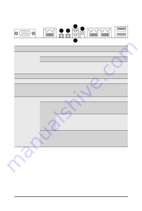
System Appearance
2-4 Rear System Button and LEDs
No.
Name
Color
Status
Description
1.
Power button
with LED
Green
On
System is powered on
Green
Blink
System is in ACPI S1 state (sleep mode)
N/A
Off
•
System is not powered on or in ACPI S5 state
(power off)
•
System is in ACPI S4 state (hibernate mode)
2.
ID Button
Press the button to activate system identification
3.
Reset Button
Press the button to reset the system.
4.
NMI button
Press the button server generates a NMI to the
processor if the multiple-bit ECC errors occur, which
effectively halt the server.
5..
System
Status LED
Green
Solid On System is operating normally.
Amber
Solid On
Critical condition, may indicate:
System fan failure
System temperature
Blink
Non-critical condition, may indicate:
Redundant power module failure
Temperature and voltage issue
Chassis intrusion
N/A
Off
System is not ready, may indicate:
POST error
NMI error
Processor or terminator missing
1
2
3
4
5
Summary of Contents for G291-2G0
Page 15: ...Hardware Installation 15 This page intentionally left blank ...
Page 21: ...System Appearance 21 ...
Page 26: ...System Hardware Installation 26 1 4 3 2 CPU1 CPU0 ...
Page 30: ...System Hardware Installation 30 For GPU1 GPU2 GPU3 GPU4 Front Rear 1 1 2 2 ...
Page 33: ... 33 System Hardware Installation For GPU5 GPU6 GPU7 GPU8 Front Rear 1 1 2 2 ...
Page 37: ... 37 System Hardware Installation 3 4 5 6 6 ...
Page 41: ... 41 System Hardware Installation 3 4 5 7 6 ...
Page 50: ...System Hardware Installation 50 This page intentionally left blank ...
Page 54: ...Motherboard Components 54 ...
Page 63: ... 63 BIOS Setup 5 2 3 Intel R Ethernet Connection X722 ...
Page 72: ...BIOS Setup 72 5 2 6 SIO Configuration ...
Page 86: ...BIOS Setup 86 5 3 1 1 Pre Socket Configuration ...
Page 89: ... 89 BIOS Setup 5 3 3 UPI Configuration ...