


- 123 -
BIOS Setup
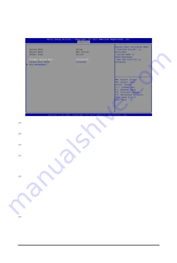
5-5-1 Secure Boot
The Secure Boot submenu is applicable when your device is installed the Windows
®
8 (or above) operating
system.
System Mode
Displays the system is in User mode or Setup mode.
Secure Boot
Displays the Secure Boot function is actived or not actived.
Vendor Keys
Displays the Vendor Keys function is actived or not actived.
Attempt Secure Boot
Secure Boot activated when Platform Key (PK) is enrolled, System mode is User/Deployed, and CSM
function is disabled.
Options available: Enabled/Disabled. Default setting is
Disabled
.
Secure Boot Mode
(Note)
Secure Boot requires all the applications that are running during the booting process to be pre-signed
with valid digital certificates. This way, the system knows all the files being loaded before Windows loads
and gets to the login screen have not been tampered with.
When set to Standard, it will automatically load the Secure Boot keys form the BIOS databases.
When set to Custom, you can customize the Secure Boot settings and manually load its keys from the
BIOS database.
Options available: Standard/Custom. Default setting is
Custom
.
Key Management
Press [Enter] for configuration of advanced items.
Please note that this item is configurable when Secure Boot Mode is set to Custom.
(Note) Advanced items prompt when this item is set to
Custom
.
Summary of Contents for G291-2G0
Page 15: ...Hardware Installation 15 This page intentionally left blank ...
Page 21: ...System Appearance 21 ...
Page 26: ...System Hardware Installation 26 1 4 3 2 CPU1 CPU0 ...
Page 30: ...System Hardware Installation 30 For GPU1 GPU2 GPU3 GPU4 Front Rear 1 1 2 2 ...
Page 33: ... 33 System Hardware Installation For GPU5 GPU6 GPU7 GPU8 Front Rear 1 1 2 2 ...
Page 37: ... 37 System Hardware Installation 3 4 5 6 6 ...
Page 41: ... 41 System Hardware Installation 3 4 5 7 6 ...
Page 50: ...System Hardware Installation 50 This page intentionally left blank ...
Page 54: ...Motherboard Components 54 ...
Page 63: ... 63 BIOS Setup 5 2 3 Intel R Ethernet Connection X722 ...
Page 72: ...BIOS Setup 72 5 2 6 SIO Configuration ...
Page 86: ...BIOS Setup 86 5 3 1 1 Pre Socket Configuration ...
Page 89: ... 89 BIOS Setup 5 3 3 UPI Configuration ...