background image

84

GERBERplotter MP Series User Manual

English

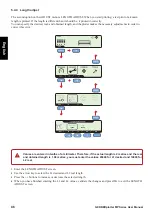
5.4.3   Print tests

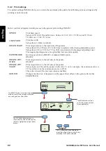
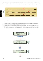
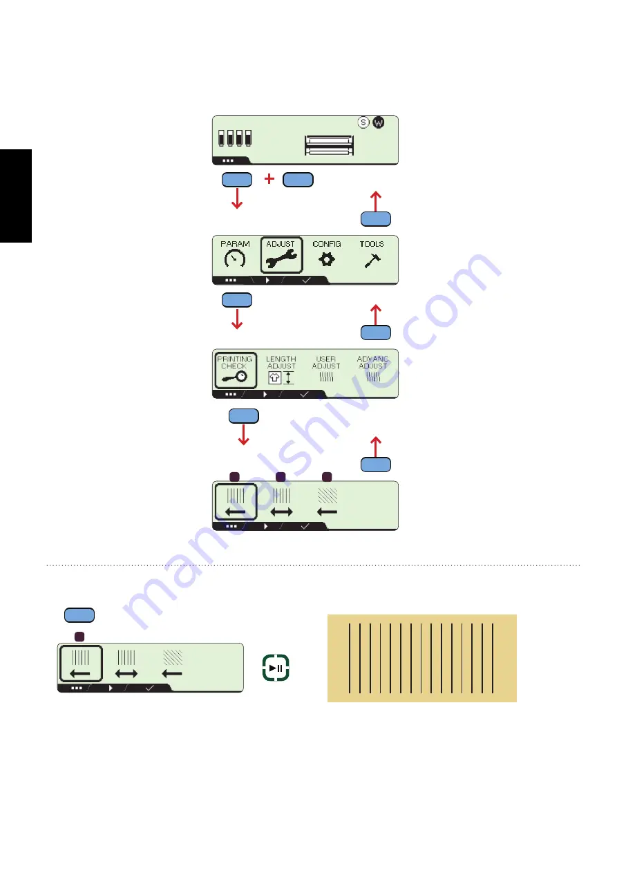
The first option in the ADJUST menu is the PRINTING CHECK, which allows you to perform a series of printing 

tests.

This option checks that all the print heads function correctly.

1

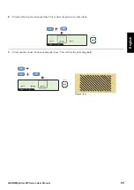
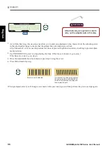
Prints unidirectional continuous lines. This verifies the print in one direction.

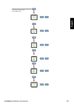
OK

1

2

3

K

K

K

K

19:49

MENU

MENU

MENU

OK

MENU

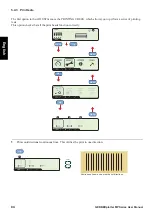
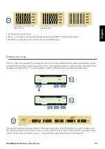
Continuous lines in one or both print directions.

1

OK

PRINT

PAUSE

Summary of Contents for GERBERplotter MP Series

Page 1: ...GERBERplotter MP Series User Manual...

Page 2: ......

Page 3: ...GERBERplotter MP Series User Manual...

Page 4: ......

Page 5: ...documentation or for inci dental or consequential damages in connection with furnishing or use of this material including for example loss of profits fabric and production time GERBERplotter is a trad...

Page 6: ...English GERBERplotter MP Series User Manual ii...

Page 7: ...equired tools 10 2 2 2 Assembly procedure 12 3 INSTALLATION AND CONFIGURATION OF THE SOFTWARE 3 1 Introduction 37 3 2 Installation 38 3 3 Configuration 44 3 3 1 Server Manager Server settings 45 3 3 2...

Page 8: ...Test encoder strip 101 5 4 10 Configuration 102 5 5 Pre printing checklist 110 6 USING THE SOFTWARE 6 1 User Interface User Manager 113 6 1 1 User Manager main window 113 6 1 2 Connecting to a server...

Page 9: ...2 Managing the firmware 157 7 2 1 Firmware back up 158 7 2 2 Updating firmware 159 7 2 3 Versions 160 7 2 4 Configuration backup 160 7 2 5 Restoring the configuration 161 7 2 6 Replacing the main boar...

Page 10: ...English GERBERplotter MP Series User Manual vi...

Page 11: ...1 GERBERplotter MP Series User Manual English 1 Introduction Technical datasheet Customer support Health and safety...

Page 12: ...2 GERBERplotter MP Series User Manual English...

Page 13: ...2 0 LAN optional Inkjet technology HP 1645 compatible Xaar optional Inkjet heads HP 1 7 2 3 4 Xaar 1 2 Paper g Starting at 20 g m2 Paper oz Starting at 0 70548oz m Noise level 40 dB File formats accep...

Page 14: ...product demonstrations software testing system training engineering and R D activities North America Phone 1 800 826 3243 toll free in USA 1 860 871 8082 outside USA 1 866 796 8570 Spanish China Phon...

Page 15: ...ow warnings and cautions Follow all other necessary safety instructions to ensure safe equipment operation Do not do maintenance alone Do not perform equipment maintenance alone Make sure another pers...

Page 16: ...otter during operation Replacing parts Notify a Gerber Field Service Representative of any broken or missing parts Do not use parts or modifications that are not approved by Gerber Scientific Inc beca...

Page 17: ...7 GERBERplotter MP Series User Manual English 2 Hardware assembly GERBERplotter MP Series description Hardware assembly...

Page 18: ...8 GERBERplotter MP Series User Manual English...

Page 19: ...irectly from the front delivery system 2 1 GERBERplotter MP Series description Paper output Ultralight aluminum take up bar up to 200 mm diameter 7 874 inch or free paper on front delivery Rapid Paper...

Page 20: ...27 CN205 CN229 CN206 CN309 Box2 CN308 Box1 CN319 Box3 CN207 CN221 CN225 CN009 The plotter packaging contains three boxes that contain small components wheels screws electronics etc Do not open these s...

Page 21: ...1 Bag 4 x 1 x 1 CN211 CN107 Bag 5 CN212 x 3 x 3 CN207 CN049 Bag 7 x 4 CN201 CN348 Bag 8 CN009 CN225 x 8 x 8 CN229 CN110 Bag 2 Some components have an attached bag containing small materials needed for...

Page 22: ...2 Assembly procedure Bag CN052 Bag 1 located on the CN227 This section details the assembly procedure for your plotter Each step identifies which components are needed and all steps must be done in o...

Page 23: ...ies User Manual English Disassemble sides Step 1 of 17 1 2 3 1 Assemble the right and left side panel and covers 2 Push cover tabs from the bottom 3 Pull the cover 4 Remove the cover CN229 CN227 1 Sep...

Page 24: ...xcept the GCB cable which has its own hole b Position the mounting notches in CN231 over the existing mounting bolts on CN227 3 Tilt CN227 until it is perpendicular to CN231 4 Install eight bolts and...

Page 25: ...ver the mounting bolts on CN229 3 Tilt CN229 until it is positioned perpendicular to CN231 4 Install eight bolts and washers using the No 4 Allen key and Bag 2 Fit the left side panel CN229 Attached t...

Page 26: ...t steps 1 to 3 for the right side panel The contents of box CN309 let you install four wheels and or four fixed support bases to the side panels A 13mm and a 17mm wrench are needed to fit the selected...

Page 27: ...he panel 3 Place the end of CN221 in the left side panel CN227 4 Fit the plastic shaft into the hole of the rear bar 5 Turn the plastic shaft to until it clicks into working position Fit the rear bar...

Page 28: ...ters use two ribbon cables and four print head plotters use three ribbon cables Warning Avoid damaging the vertical strip encoder 1 Unpin the rear protector 2 Rotate the protector 90 degrees 3 Without...

Page 29: ...8 Inverter Dampers Step 7 of 17 1 Fit the inverter in the upper hole of the left side panel CN229 2 On both side panels mount the two buffers Buffers help the front cover close smoothly The position o...

Page 30: ...ar of the assembly b Fit piece CN211 horizontally between the two side panels and below the inverter 2 Lower CN211 horizontally until it fits into the outer edge of CN231 3 Torx T30 CN107 Bag 5 Fix bo...

Page 31: ...er bridge while the printer is in operation 1 Position CN212 to the front of the assembly at the same height as the rear cover and slide CN212 towards the rear until it fits in CN227 and CN229 2 Open...

Page 32: ...the motor as indicated and fix it to the right side panel from the inside using the three bolts and washers supplied The traction bar redirects the paper so it can roll Install the right side of the...

Page 33: ...he right side panel CN227 3 Torx T20 CN348 Bag 8 Install the cover using two screws for each side 4 Close the cover This cover contains five wheels that are mounted to permit some freedom of movement...

Page 34: ...N009 on top of the wheels in the right side panel Install the paper take up bar in front of the cover Having the paper take up bar free at one end lets you quickly remove a job To remove a job cut the...

Page 35: ...the bar CN225 onto the flat side of the support 2 Slide the bar into the locations shown As an option you can supply an additional paper support bar that allows the operator to switch between differen...

Page 36: ...these to the electronics that control the plotter The electronics in CN319 box 3 include the plotter display unit the net filter the power supply cable and the master board This set is integrated int...

Page 37: ...epends on the number of print heads in the plotter Plotters with two print heads use flat cables CON8 and CON9 while plotters with four print heads add cable CON10 Coming from the upper motor paper te...

Page 38: ...ic assembly Step 14 of 17 1 Place the electronic panel connections hub into the lateral leg connection hole CH 2 Turn and push the connection panel to clip it in place Install the electronic panel 1 2...

Page 39: ...e upper motor to the CON3 connector 4 Connect the cable from the top cover to the CON43 connector on the main board 5 Connect the RFID cables to CON28 red coded cable matching the red coded connector...

Page 40: ...30 GERBERplotter MP Series User Manual English Connections Step 15 of 17 1 2a 2b 2d 2e 2f 2c CON 10 CON 9 CON 8 15...

Page 41: ...31 GERBERplotter MP Series User Manual English Connections Step 15 of 17 CON 22 CON 3 CON 23 CON 43 CON 28 CON 29 CON 5 15...

Page 42: ...embly of the plotter install covers on both side panels Secure each cover using six washers and bolts 1 Fit the cover to the right side panel 2 Put the square into the centering holes 3 Repeat the sam...

Page 43: ...33 GERBERplotter MP Series User Manual English Feet 1 2 CLICK 1 Orient the part as shown in the picture 2 Insert the part as shown until you hear a click Step 17 of 17 17...

Page 44: ...34 GERBERplotter MP Series User Manual English...

Page 45: ...35 GERBERplotter MP Series User Manual English 3 Software installation and configuration Introduction Installation Configuration...

Page 46: ...36 GERBERplotter MP Series User Manual English...

Page 47: ...e 20 MB Processor speed 1 5 GHz Optional Internet connection for software updates The necessary minimum requirements for your computer are as follows A typical working environment comprises a plotter...

Page 48: ...dministrator More specific configurations are detailed in the section Software configurations 3 2 Installation Snapshots All pictures of computer screens were taken us ing Windows 7 What you see might...

Page 49: ...install or uninstall Double click update exe to start the installation If you do not have sufficient authorization to perform the installation the system displays a warning message You should start t...

Page 50: ...t appear during the installation process Since you are performing a controlled installation you can accept these requests If needed software required to run User Manager and Server Manager is installe...

Page 51: ...41 GERBERplotter MP Series User Manual English During the installation process dialog boxes display messages about installation status errors or both...

Page 52: ...ion process The following diagram shows the installation process for Visual C 2008 Redistributable software which is required to use the plotter The installer automatically starts an installation wiza...

Page 53: ...tallation of the plotter driver causes a warning message Click Install the driver software anyway and allow the process to continue because you can trust the source of the files being installed 3 Afte...

Page 54: ...ther computer or manage multiple plotters from a single Server Manager installation For a detailed description on using the User Manager and Server Manager please see the User Interface User Man ager...

Page 55: ...English 3 3 1 Server Manager Server settings This dialog box lets you edit the connection configuration From the main screen of Server Manager you can access the connection configuration default sett...

Page 56: ...ption and change the default ID value 1111 to identify each connec tion accurately Reuse queue When this option is enabled the job queue managed by User Manager is maintained if Server Manager is rest...

Page 57: ...y Similar to the previous option but here the list of IP addresses corresponds to computers that are not allowed connect to Server Manager IP Ad dress Lets you enter the IP address of the computer to...

Page 58: ...table name 3 For each additional connection a new port must be established to the ones already being used in the other con figurations 4 Alternatively the other options for each connection can be modi...

Page 59: ...ver Manager communicates with the plotter through one communication port Asingle plotter connected to Server Manager uses port 9999 by default Each additional plotter must be assigned a different port...

Page 60: ...ter ID is 11111 which doesn t refer to any plotter in particular To use more than one plotter select the Multiplotter check box This lets you enter the plotter ID as sociated with the connection The b...

Page 61: ...new server and click configuration 2 Enable the multiplotter option 3 Define a Plotter ID value that corresponds to that particular plotter 4 Define a unused port 5 Open User Manager 6 Click Program...

Page 62: ...ter that runs Server Man ager You need to know the IP address for the Server Manager computer 1 Open User Manager 2 Click Program Options Connections 3 Clear the Server and user in the same computer c...

Page 63: ...ons for each of the plotters 1 Open Server Manager add a new server and click configuration 2 Enable the multiplotter option 3 Define a Plotter ID value that corresponds to that particular plotter 4 D...

Page 64: ...final activation code is returned and displays at the bottom of the dialog box e g 014F0E0DWKJ7AU22 7 Click Accept to complete the registration A dialog box confirms successful registration If a final...

Page 65: ...55 GERBERplotter MP Series User Manual English 4 Updating WinPlot or AccuMark...

Page 66: ...56 GERBERplotter MP Series User Manual English...

Page 67: ...up in User Manager and Server Manager soft ware Log on to the computer that has WinPlot or AccuMark using an administrator account 4 3 Installing the Software Update To install the update you need the...

Page 68: ...publisher dialog box b When prompted that the publisher could not be verified click Run to run the update c When prompted to allow the program from an unknown publisher to make changes to the computer...

Page 69: ...er update h When prompted click Finish to close the setup dialog box 5 Configure Windows to make the GERBERplotter MP Series available a Open Windows Control Panel The steps to do this vary based on y...

Page 70: ...Click Hardware and Sound Accessing GerberDevices d Click GerberDevices 32 bit e When prompted to allow changes to the computer click Yes The Gerber Device Configuration dialog box opens f Click the Pl...

Page 71: ...s WinPlot and AccuMark can now use the GERBERplotter MP Series 6 Reboot the computer 4 4 Using WinPlot and AccuMark To use the GERBERplotter MP Series with WinPlot or AccuMark after you install the up...

Page 72: ...62 GERBERplotter MP Series User Manual English...

Page 73: ...63 GERBERplotter MP Series User Manual English 5 Plotter operation Loading a roll of paper Paper run Removing the paper Display Pre printing checklist...

Page 74: ...64 GERBERplotter MP Series User Manual English...

Page 75: ...irection Paper roll orientation for loading onto paper roll support bar Fit paper roll Step 1 of 4 1 1 Allen key n 6 Loosen the left cone on the paper roll support bar and slide it off completely 1 2...

Page 76: ...e ar row is pointed directly towards the white arrow of the right cone 2 Ensure that the left and right cones are firmly fixed in position and that the screws are tight ened Push both cones into the c...

Page 77: ...1 Allen key n 6 Loosen the left and right cones on the paper support bar 3 Allen key n 6 Using the Allen key provided firmly tighten the left and right cones on the paper support bar Once the paper ro...

Page 78: ...r up and over the print ing base 2 Slide the paper towards the rear of the printer bridge as shown in the diagram Check the tension on both sides of the paper The tension should be uniform and suffici...

Page 79: ...ter bridge up to the drive bar and slides it through to the front of the ma chine In this case it is assumed that the paper is to be fed onto a paper take up bar with the inverter in the standard posi...

Page 80: ...p 5 of 5 5a For standard paper collection The inverter on the plotter is used to determine the direc tion of rotation of the paper take up bar It allows you to choose whether you have the printed side...

Page 81: ...oth sides of the paper using the side clips in the vertical position The paper enters through the up per gap in the wing of the fastener running over the wing on the inside of the paper support bar an...

Page 82: ...in the inverted position see the picture in the right side of page and the paper path from paper pull to the take up bar see the picture in the left side of page Step 5 of 5 5b Paper collection invert...

Page 83: ...ar 2 4 Fasten the paper on both sides with the side fastening clips in the vertical position The paper enter through the lower gap in the wings of the fastener run over the wing on the inside of the p...

Page 84: ...process of removing the paper from the paper take up bar after the jobs have been printed There are different ways to wind the paper roll to set the printing jobs in the correct position to allow an a...

Page 85: ...r keyboard The paper automatically advances to be attached to the take up bar using the side and center clips 4 When the paper stops hold the paper using the side and center clips PAPER 1 After the la...

Page 86: ...ne is between the motorized tube and the paper take up bar 4 The plotter pauses printing letting you cut and remove the paper roll containing the finished jobs At the same time the PRINT PAUSE and STO...

Page 87: ...me time the PRINT PAUSE and STOP LEDs of the plotter keyboard blink indicating you can cut the paper and remove the printed job 3 After the plotter stops cut the paper along the dashed line The finish...

Page 88: ...cut is printed Then printing resumes normally after a little paper advance 1 From User Manager go to the printing queue and add the CUT PAUSE modifier after the job you want to extract User Man 3 Once...

Page 89: ...nd slide the paper outside the take up bar 3c 4 Once the paper roll is completely off the take up bar place the right side clip on the bar to the approximate position it was before and leave the tube...

Page 90: ...tter has been stopped it resumes printing Starts and pauses print jobs and calibration tests STOP Stops printing Puts the plotter in STOP mode so the plotter cannot receive new jobs MENU Accesses to t...

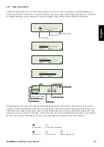
Page 91: ...the color varies depending on the financing state of the machine 5 4 1 Start and self test Starting the plotter takes a few seconds during which time various checks are performed to supply informatio...

Page 92: ...0 and 200 cm s Values of 19 68 39 37 59 05 in and 78 74 in s 50 200 cm s 19 68 78 74 in s LINE WIDTH Print line width Values from 1 thin to 4 thick ORIGIN RIGHT Print origin relative to the right side...

Page 93: ...83 GERBERplotter MP Series User Manual English OFF 2790 3 HQ 200 334 3 OFF 2790 3 HQ 200 334 3 The arrow button selects the next available option HQ 200 334 3...

Page 94: ...CHECK which allows you to perform a series of printing tests This option checks that all the print heads function correctly 1 Prints unidirectional continuous lines This verifies the print in one dire...

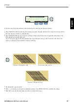
Page 95: ...Manual English 2 Prints bidirectional continuous lines This verifies the print in two directions 3 Prints unidirectional continuous diagonal lines This verifies the print diagonally OK 2 Diagonal lin...

Page 96: ...to correct this error 1 Enter the LENGTH ADJUST screen 2 Use the arrow key to select the L1 desired and L2 real length 3 Press the buttons to increase or decrease the selected length 4 When you have f...

Page 97: ...changing the angle of the print head using a screwdriver the screw shown in the picture For the rest of the steps the adjustments are numerical and the values are entered according to the results of t...

Page 98: ...ith respect to the movement of the print head The plotter screen also shows the buttons to use while making these adjustments PRINT PAUSE and OK No 4 Allen key A No 4 Allen key is required in order to...

Page 99: ...eft of the print head carriage and then repeat the print Screw correctly adjusted 2 Overlap The second step of User adjust OVERLAP lets you adjust the values for horizontal alignment between the diffe...

Page 100: ...adjustment values is done as follows 1 Pressing increases or decreases the adjustment value of the selected pairing indicated by frame symbol Select the most accurate pairing for example pairing 6 in...

Page 101: ...step 1 As with the previous adjustments press PRINT PAUSE to print a test Visually determine the value between 0 and 29 that best shows a continuous horizontal line in this case 7 Only values near to...

Page 102: ...he lines produced by the print head moving in one direction or the other and increase or decrease the adjustment values accordingly when the lines join together 3 If printing to the left produces more...

Page 103: ...of print heads A series of vertical lines is printed and you choose the correct value continuous lines A plotter with two print heads shows an adjustment value for PH 1 2 in this example 2 and the di...

Page 104: ...ated print heads PH 1 2 When the print is finished visually determine the value that shows the best and most continuous lines 1 and 2 in the examples 2 Press increases or decreases the adjustment valu...

Page 105: ...justments are repeated to make the necessary changes for the rest of the paired print heads PH 2 3 and PH 3 4 0 1 3 4 2 OFFSET PH 2 3 PH 2 3 2 3 5 6 4 OFFSET PH 3 4 PH 3 4 PH2 3 7 PH3 4 7 PH2 3 7 OK O...

Page 106: ...ments in this step PRINT PAUSE OK PRINT PAUSE 1 As with the first step this step does not allow you to enter an adjustment value Instead turn the adjusting screw in the print head carriage to ensure t...

Page 107: ...th directions of print head movement The lines should join together perfectly If not look at the gaps in the lines produced by the print head moving in one direction or the other and increase or decre...

Page 108: ...MP Series User Manual English 5 4 6 Auto test K K K K 19 49 MENU MENU OK MENU OK TEST 5 SUCCEEDED Press OK to start the self test Wait until it finishes The self test option enables a general plotter...

Page 109: ...AV 0 0 A PK 3 7 A CS 0 5 A Start the motor X test PRINT PAUSE Finalize the X motor test STOP Motor X moves the print head The test motor X option shows The average current consumption by motor X The p...

Page 110: ...S 0 1A OK Start the Y motor test PRINT PAUSE Finalize the Y motor test STOP Motor Y moves the paper The test motor Y option shows The average current consumption by the paper motor and GCB motor The p...

Page 111: ...s any damage on the encoder strip the carriage stands at the detection point indicating the position of the fault If the test finds a fault call your Gerber Representative to replace the encoder strip...

Page 112: ...the CONFIG menu you can change the language used in the plotter display adjust the date and time settings used by the system and modify the IP address to be used for a network connection Use this menu...

Page 113: ...plotter MP Series User Manual English Language OK K K K K 19 49 OK Use the LANG option to change the language of the display Select one of the languages available in the plotter firmware OK MENU MENU...

Page 114: ...104 GERBERplotter MP Series User Manual English Date time setting K K K K 19 49 OK 1 6 5 5 1 8 0 1 0 7 1 4 OK Use the SET TIME option to change date and time OK MENU MENU MENU MENU...

Page 115: ...105 GERBERplotter MP Series User Manual English IP address K K K K 19 49 OK 192 168 0 165 Use the IP ADDRESS option to change the IP address of your plotter OK MENU MENU MENU OK MENU...

Page 116: ...106 GERBERplotter MP Series User Manual English Warranty K K K K 19 49 OK OK BNQ549VF Use the ABOUT option to access plotter ID and warranty status MENU MENU MENU MENU MENU OK...

Page 117: ...English Firmware version K K K K 19 49 OK OK Use the ABOUT option to access FIRMWARE VERSION for all MCUs in the plotter FIRMWARE VERSIONS MCU 1 5 5 0 MCU 2 2 3 1 MCU 3 0 0 0 MCU 4 1 2 3 MCU 5 1 2 3...

Page 118: ...108 GERBERplotter MP Series User Manual English Plug ins K K K K 19 49 Use the ABOUT option to access the PLUG INs option to see all the current installed options MENU MENU MENU MENU OK OK...

Page 119: ...l English Activate Plug ins To activate a plug in bring the RFID card within range of the antenna near the top of the right side cover and wait for the OK symbol Approach the card and wait OK symbol t...

Page 120: ...een damaged in transit so it won t handle the paper properly 4 Ensure that the tension on both sides of the paper is uniform so the paper to can advance without any wrinkles See Loading a roll of pape...

Page 121: ...111 GERBERplotter MP Series User Manual English 6 Using the software User interface User Manager Plotter server Server Manager...

Page 122: ...112 GERBERplotter MP Series User Manual English...

Page 123: ...cess User Manager directly from your desktop or through the Windows Start menu For a proper connection between client and server start Server Manager first User Manager tries to connect with Server Ma...

Page 124: ...the refresh mode for the different connections and to perform different tasks with the jobs in the print queue change position delete Customer pro grams Allows you to display the status of the curren...

Page 125: ...bbin full Front cover closed Close the front cover to continue printing Indicator lights show when the plotter is not connected The status indicators for the ink cartridges from 1 4 are next to the pa...

Page 126: ...otter status Finally the queue displays the status of three plotter options Finance Warranty and Service Saver After you buy an option for the plotter you receive a service note that explains the opti...

Page 127: ...which you ac cess from Program options Connections see the 3 3 4 User Manager connections manager Press to connect to The Refresh option in the Queue menu initiates an attempt to connect to Server Man...

Page 128: ...ed in the user column when sending files to the job queue default values are used if they are sent directly Finally the Time Status and Ink columns show an estimation of the time necessary to print al...

Page 129: ...n the print queue the plotter prints a dashed line after that job to show where to cut the paper The next available job is sent to the plotter When the dashed line indicating a cut reaches the cutting...

Page 130: ...cut modifier is used 1 6 2 7 3 4 5 8 1 Removes selected elements from the print queue Delete file and group files removes all elements associ ated with the same group 2 Moves the selected job up or do...

Page 131: ...1 11 1 Allows you to select a file and add it directly to the job queue This is the same as selecting Direct print Ctrl P from the Print menu 1 2 The area below the job queue displays information abo...

Page 132: ...option to place a file directly into the jobs queue using default parameters Direct print 1 In the main menu of User Manager click Program Options Con nections 2 Select the PLOTTER DEFAULT connection...

Page 133: ...parameters dialog box displays the default parameters You can modify the parameters before sending the job to the queue select parameters Preview The dialog box lets you view the contents of the file...

Page 134: ...individually When the file list is complete send the resulting compo sition to the job queue If needed assign a name to the job 1 Click Print Options Composition and print 2 If file selected is corre...

Page 135: ...and send them to the job queue to gether The resulting composition appears in the job queue The Add multiple files option allows you to send multiple files using the default settings An HPGL vector fi...

Page 136: ...or files you use often Drag and drop User Manager lets you drag HPGL and ISO files onto the job queue The files use default parameters Files that produce a rasterizing error are not added to the job q...

Page 137: ...fault settings Click Program options Default settings to set the default settings that are used when sending files directly to the job queue The Direct print option uses these defaults The table in th...

Page 138: ...ts are not allowed Print width and height Scale Set a scale applied to the print job Values other than 100 are shown in red in the job queue File Copies Set the number of copies of a job sent to the p...

Page 139: ...sion when viewing markers through the file browser Additionally if a marker corresponds to a HPGL or ISO marker its type is automatically identified Extensions Format Selects the format of extensions...

Page 140: ...w Print and Composition and print options let you modify the default settings before sending a job to the print queue The file dialog box uses the User Manager settings established in Program options...

Page 141: ...ale units or rotation 6 1 7 Language and units User Manager lets you specify the language and the units used by the program Click Configuration and Language to display units in two expandable lists Th...

Page 142: ...files define two languages English and Spanish The select languages list displays lang file names You can use a text editor such as Notepad to edit the files In the diagram below you can see the stru...

Page 143: ...inator Units Final size without cut Calculates the size of the job to be sent to the plotter based on units and denominator The denominator is the quantity of points by mm or inch If you use inch 40 e...

Page 144: ...rt used to connect with Server Manager the date and time they were added to the job queue and a status indicator Possible status descriptions shown in history Excess width error The file exceeds the m...

Page 145: ...r overcurrent protection Serious excess motor consumption for electrical or mechanical rea sons Failure Encoder strip reading error Serious error reading encoder strip The encoder strip is dirty or de...

Page 146: ...d added to the job queue using default parameters see 6 1 3 Sending jobs to the plot ter 2 You can also use the pattern subfolder for small jobs You can manually group them together to generate compos...

Page 147: ...omposition giving time to receive more files that could be included in the same composition A value that is too short could prevent subsequent files from being added A value that is too long could del...

Page 148: ...n of files is automatic upon reception or must be done manu ally Manual composition You can check to see if the automatic send function is working by placing files in the specified folder Within a few...

Page 149: ...ter the following values in the dialog From the entered values User Manager calculates the necessary correction and applies them to the next set of jobs sent to the plotter Send a job of a known size...

Page 150: ...nce marker should produce a result where the desired values match the obtained values Plotter calibration Square 1500x2000 Print a square of this dimension Square 1000x1000 Print a square of this dime...

Page 151: ...programs Plugins and options to access plotter options This menu shows the options currently on the connected plotter Access to other options Finance Warranty and Service Saver is only available afte...

Page 152: ...perform tasks such as stop restart and disconnect existing connections You can also add a connection for each additional plotter you want to control The default connection when installing Server Manag...

Page 153: ...for the first time the operating system could display a firewall message indicating that it has blocked communication with the local network 3 When running Server Manager you should config ure your fi...

Page 154: ...Server Manager Lan guage Allows you to choose the language used by the Server Manager interface Servers Language New server Allows you to add a new server Delete server Allows you to delete an existin...

Page 155: ...st be at least one connec tion at all times The icons allow you to modify the parameters for each connection and to manage the firmware of the plotter Connections list This list displays all the conne...

Page 156: ...y Server Manager The method used to change languages or to add a new language is similar to that explained in section 6 1 7 except that you must work with files from the folders derived from the plott...

Page 157: ...sh 6 2 4 Information about versions Click the question mark icon in the options menu to get information about Server Manager Click the icon in the left corner of the job queue section for Server Manag...

Page 158: ...148 GERBERplotter MP Series User Manual English...

Page 159: ...149 GERBERplotter MP Series User Manual English 7 Operation and maintenance Managing software Managing firmware Cleaning and preventative maintenance...

Page 160: ...150 GERBERplotter MP Series User Manual English...

Page 161: ...to install or uninstall to open the installation wizard Updating the software used by the plotter is similar to the original installation 7 1 Managing software Run update exe to start the installation...

Page 162: ...programs option and click Next 3 The installation wizard lets you install Server Manager and User Manager together All programs option or separately Server and User options respectively Addi tionally...

Page 163: ...153 GERBERplotter MP Series User Manual English The following are examples of some messages that might appear when updating Server Manager or User Manager...

Page 164: ...tion has completed and finally click Close to exit the instal lation wizard When you choose to update User Manager the installation process displays a wizard that details the tasks being completed Dep...

Page 165: ...date process also lets you uninstall User Manager and or Server Manager delete configura tion settings or reinstall the plotter driver These processes generally only require confirmation and don t ins...

Page 166: ...e 2 Install driver This lets you install a plotter driver During a trouble free update the last step of the installation wizard ends with messages similar to the ones shown here so you can see that Se...

Page 167: ...hat this process be performed by a qualified technician Use Server Manager to update the plotter firmware Server Manager must be connected by a USB cable to the plot ter you are updating and only one...

Page 168: ...o the backup if needed To perform a backup 1 Click the ellipsis button to open the FW UP dialog box 4 If the plotter is turned on and connected to Server Man ager click the backup icon to transfer the...

Page 169: ...the driver is not installed run the update program and follow the installation steps the installation procedure is explained in section 6 1 2 The update process uses the plotter DFU driver Confirm tha...

Page 170: ...am version server version raster version and firmware version 7 2 4 Configuration backup Information concerning the configuration and calibration of the plotters is kept in the internal memory EEPROM...

Page 171: ...settings such as information and calibration data 1 Make a copy of the security configuration see section 7 2 4 Configuration backup 2 Disconnect the plotter and replace the main board 3 Restore the...

Page 172: ...162 GERBERplotter MP Series User Manual English...

Page 173: ...163 GERBERplotter MP Series User Manual English 8 Troubleshooting Plotter error list Software Mechanics electronics...

Page 174: ...164 GERBERplotter MP Series User Manual English...

Page 175: ...that nothing is blocking the movement of the printer bridge along the X axis Paper motor If there is no problem with the paper motor response the CPU wait for the Y motor response If the paper doesn t...

Page 176: ...cking on the Preview and print option you can modify files Can I modify the print settings of a file after it has been sent to the job queue Select the file and click the modify button to see which se...

Page 177: ...ror 1 Verify the markers have the correct dimensions You can use Preview and print function in the print menu 2 Change the units and divisor in the extension menu if necessary You can send files in wh...

Page 178: ...r tridge with a new one to verify this 3 Be sure that the rear cover fixing screw is in stalled correctly There are wrinkles in the paper Verify the top cover wheels are loose and turn easily Paper ha...

Page 179: ...169 GERBERplotter MP Series User Manual English 9 Glossary...

Page 180: ...170 GERBERplotter MP Series User Manual English...

Page 181: ...ss Internet Protocol address Numerical address assigned to each device e g com puter printer participating in a computer network that uses the Internet Protocol for communication IP ad dresses are bin...

Page 182: ...out by the plotter during start up The plotter display shows the possible errors found along with the unique identification number associated with each machine used when configuring multiple plotters...

Page 183: ......
Page 184: ...Corporate Headquarters Gerber Scientific Inc 24 Industrial Park Road West Tolland CT 06084 USA Tel 1 860 871 8082 Fax 1 860 871 3820 www gerbertechnology com PN v1 0 3 10 14...

Reviews:

Related manuals for GERBERplotter MP Series