26
GERBERplotter MP Series User Manual
English
Electronic assembly
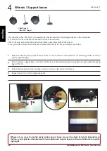
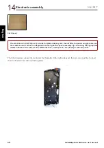
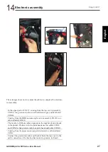
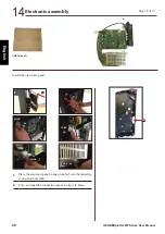
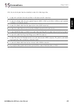
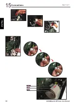
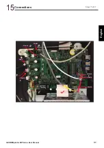
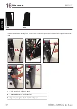
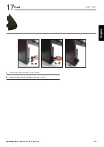
The following steps connect the electronics for the plotter. In the right side panel, there are eleven cables. Connect
these to the electronics that control the plotter.
The electronics in CN319 (box 3) include the plotter display unit, the net filter, the power supply cable, and
the master board. This set is integrated into the right-side panel assembly by connecting the appropriate
cables. Cables for the lower motor, RFID antennas, and top cover are already in the side panel.
Step 14of 17
CN319 (box 3)
14
Summary of Contents for GERBERplotter MP Series
Page 1: ...GERBERplotter MP Series User Manual...
Page 2: ......
Page 3: ...GERBERplotter MP Series User Manual...
Page 4: ......
Page 6: ...English GERBERplotter MP Series User Manual ii...
Page 10: ...English GERBERplotter MP Series User Manual vi...
Page 12: ...2 GERBERplotter MP Series User Manual English...
Page 18: ...8 GERBERplotter MP Series User Manual English...
Page 44: ...34 GERBERplotter MP Series User Manual English...
Page 46: ...36 GERBERplotter MP Series User Manual English...
Page 65: ...55 GERBERplotter MP Series User Manual English 4 Updating WinPlot or AccuMark...
Page 66: ...56 GERBERplotter MP Series User Manual English...
Page 72: ...62 GERBERplotter MP Series User Manual English...
Page 74: ...64 GERBERplotter MP Series User Manual English...
Page 122: ...112 GERBERplotter MP Series User Manual English...
Page 158: ...148 GERBERplotter MP Series User Manual English...
Page 160: ...150 GERBERplotter MP Series User Manual English...
Page 172: ...162 GERBERplotter MP Series User Manual English...
Page 174: ...164 GERBERplotter MP Series User Manual English...
Page 179: ...169 GERBERplotter MP Series User Manual English 9 Glossary...
Page 180: ...170 GERBERplotter MP Series User Manual English...
Page 183: ......

