background image


 32 

2.8  Firmware Upgrade 

GeoVision will periodically release the updated firmware on the website. The new firmware 
can be simply loaded into the reader by using

 Update Utility


included in the Software CD. 


Important Notes before You Start  

Before you start updating the firmware, please read these important notes:  

1.  While the firmware is being updated, the power supply must not be interrupted. 

2.  Do not turn the power off within 10 minutes after the firmware is updated.   


WARNING:

 The interruption of power supply during updating causes not only update 

failures but also damages to the device. In this case, please contact your sales 
representative and send your device back to GeoVision for repair. 

 
To upgrade firmware: 

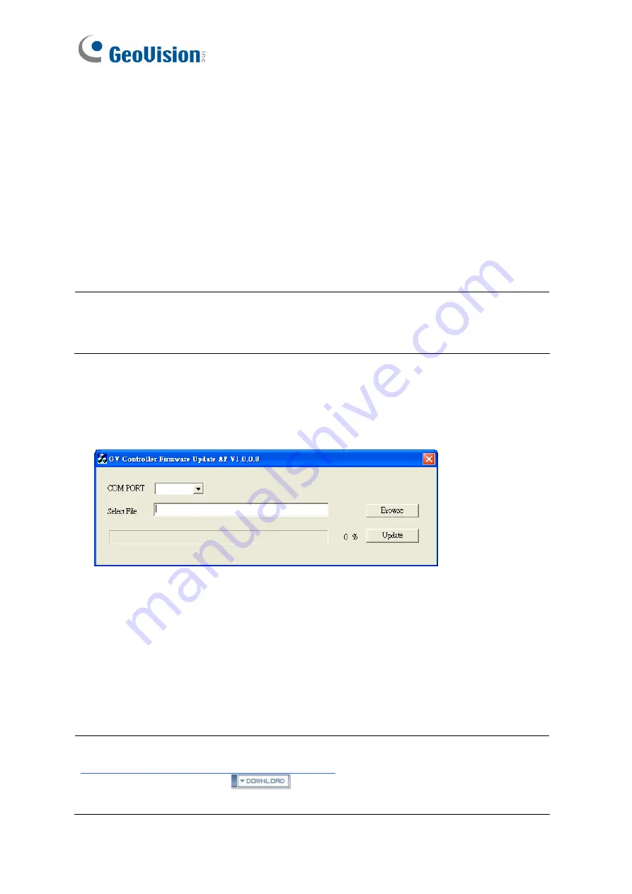
1.  Insert the Software CD and select 

Run Firmware Update Utility

. This dialog box 

appears. 


2.  Select the COM port of the reader. 

3. Click the 

Browse 

button to locate the firmware file (.bin) saved at your local computer. 

4. Click 

Update

5.  The LED indicator should flash purple during the process of firmware upgrading. When 

the process is complete, the reader will be sounded twice and the LED indicator will 
change to green. 


Note:

 You can also download the firmware upgrade utility from the GeoVision website: 

GV-Reader

 from the drop-down 

list, click the 

Download 

icon 

 of 

GV-RK1352 & GV-R1352 & GV-DFR1352 

Firmware Upgrade Utility

Summary of Contents for 520-R1251-000

Page 1: ...GV Card Reader Before attempting to connect or operate this product please read these instructions carefully and save this manual for future use User s Manual READER C...

Page 2: ...ty is assumed for incidental or consequential damages arising from the use of the information or products contained herein Features and specifications are subject to change without notice Note No memo...

Page 3: ...ice complies with Part 15 of the FCC Rules Operation is subject to the following two conditions 1 This device may not cause harmful interference and 2 This device must accept any interference received...

Page 4: ...i Preface Welcome to the GV Card Reader User s Manual This Manual applies to the following GV Card Readers Reader Models GV Reader1251 and 1352 V2 GV SR1251 GV RK1352 R1352 Card Reader GV DFR1352 Rev...

Page 5: ...rface 6 1 3 3 Connecting to GV DVR NVR and Third Party Access Controllers 8 1 4 Overlaying Card Numbers on GV DVR NVR Live View 9 1 5 Changing the Default Settings of Beeper and LED 10 1 6 Specificati...

Page 6: ...ding the Reader to GV DVR NVR 25 2 6 Changing the Default Settings of Beeper and LED 26 2 6 1 Setting up Beeper and LED on GV R RK DFR Config AP 26 2 6 2 Wiring the Beeper and LED to the GV AS Control...

Page 7: ...ndicator is controllable by the host system and changes from red to green to indicate access granted The GV Reader1251 1352 V2 SR1251 also has a host controllable buzzer 1 1 Packing List If any of the...

Page 8: ...trol is the internal control When the setting is On the Reader is sounded after a card is read When the setting is Off the Beeper is controlled externally You can use the external beeper control line...

Page 9: ...der is controlled by Wiegand signal When the setting is Off the Reader is for RS 485 signal SW5 SW7 ID Setting Switch 5 to switch 7 is used to set the Reader s ID during a chain connection ID 0 1 2 3...

Page 10: ...DFR Config AP 3 Select the COM port that is connected to the reader and click Open COM The red square next to the COM port box should change to blue to indicate the COM port is correct 4 Select an ID...

Page 11: ...access controller ensure the related switch setting on the GV Reader1251 1352 V2 is configured correctly Note Each reader consumes 60 mA of power The total power consumption of the output devices and...

Page 12: ...AS Controller through a single RS 485 cable When you connect more than one GV Reader to the GV AS Controller on the last connected GV Reader turn SW8 to ON Make sure to define the ID of each reader w...

Page 13: ...he GV AS Controller 1 Type the GV AS Controller s IP address in the Web browser 2 Type the username and password to login 3 In the left menu click Extended Reader This page appears 4 If the readers ar...

Page 14: ...the access controller through the Wiegand interface connect the reader to the GV DVR NVR via GV COM GV Hub or GV NET IO Card V3 1 Note The GV Reader1251 1352 V2 SR1251 is not compatible with the GV NE...

Page 15: ...refer to 2 5 Overlaying Card Numbers on GV DVR NVR Live View GV HUB GV COM GV NET IO Card GV DVR NVR Light Blue RS 485 Blue RS 485 USB GV Reader1251 1352 V2 SR1251 Note 1 For GV Reader1251 1352 V2 ma...

Page 16: ...and LED by using the GV R RK DFR Config AP For details refer to 2 6 1 Setting up Beeper and LED on GV R RK DFR Config AP 2 For GV Reader1251 1352 V2 enable external control of the reader s Beeper and...

Page 17: ...d Green Blue LED Red Green LED Beeper Buzzer Frequency 125 KHz Proximity EM Card 13 56 MHz for ISO14443A Mifare Class RS 485 9 600 bps connect up to 8 GeoVision readers GV CR420 GV Reader1251 GV SR125...

Page 18: ...th GV ASNet Not supported Not supported GV AS210 2110 2120 4 8 GV AS410 4110 8 8 GV AS810 8110 8 16 GV EV48 Not supported 2 GV CS1320 Not supported 2 1 6 2 The number of GV Reader 1352 V2 supported by...

Page 19: ...ds GV RK1352 comes with keypad allowing it to also recognize PIN codes GV DFR1352 is designed to be installed on the door frame Featured with the Wiegand and RS 485 outputs the readers can be connecte...

Page 20: ...are CD 6 Installation Guide 7 Warranty Card GV R1352 1 GV R1352 Card Reader 2 Screw x 3 3 Screw Anchor x 2 4 Security Torx 5 Software CD 6 Installation Guide 7 Warranty Card GV DFR1352 1 GV DFR1352 Ca...

Page 21: ...ellow Beeper Orange Green LED Light Red Red LED Green Wiegand Data 0 White Wiegand Data 1 Blue RS 485 Light Blue RS 485 Rear View GV R1352 Wire Color Function Red DC 7 5 12V Black GND Yellow Beeper Or...

Page 22: ...ta 0 White Wiegand Data 1 Blue RS 485 Light Blue RS 485 Gray N A Purple N A Brown N A Rear View Install the GV DFR1352 to the door frame using the supplied screws and screw anchors Before placing and...

Page 23: ...cator and Beeper In standby mode the LED is blue When a card is read the LED flashes green and the beeper beeps once The reader comes with external control wires for Green LED Red LED and Beeper You c...

Page 24: ...erface GV AS210 2110 2120 410 4110 810 8110 through Wiegand or RS 485 interface 2 Each GV RK1352 R1352 DFR1352 consumes 60 mA of power The total power consumption of the output devices and readers con...

Page 25: ...5 Blue RS 485 Red DC 7 5 12V RS485 12V A A B B GND Reader 1 Black Light Blue Blue Red Reader 4 GV AS810 Controller GV RK1352 or GV R1352 Connecting five or more readers to GV AS810 Controller For read...

Page 26: ...u can also set the reader to read the GID or UID on GV AS ID Cards Key Fobs Note that the Web interface of different GV AS Controller models varies 1 On the controller s Web interface click Extended R...

Page 27: ...own below If there is only one number on your GV AS ID Cards Key Fobs GID is not supported and you must select Unique Identification UID 5 Click Submit Note 1 When you click Submit on the Extended Rea...

Page 28: ...o install GeoVision USB Device Driver Installing from Software CD 1 Insert the software CD and the Install Program window will pop up automatically 2 Select Install GeoVision USB Device Driver 3 In th...

Page 29: ...HUB GV COM GV NET IO Card RS 232 GV System Light Blue RS 485 Blue RS 485 USB GV RK1352 or GV R1352 Note GV RK1352 R1352 DFR1352 is not compatible with GV NET Card and GV NET IO Card of versions earlie...

Page 30: ...the GV DVR NVR you need to set up a unique ID number for each reader For this you need to connect each reader to the computer one reader at a time and follow the instructions above to set up an ID num...

Page 31: ...s dialog box appears 2 Click the New button This dialog box appears Type Select GV Wiegand Capture Device Type a number and name to help you identify the reader COM Select the COM port connected to th...

Page 32: ...D from the reader to the GV AS Controller 3 Specify the Beeper and LED settings for each door through the Web interface of GV AS Controller 2 6 1 Setting up Beeper and LED on GV R RK DFR Config AP To...

Page 33: ...page of the GV AS Controller Web interface 6 Click Setup The settings are sent to the reader The serial number and the firmware version of the reader will be automatically detected If you want to set...

Page 34: ...0 as an example For Red LED use the light red wire instead Wire Color Function Black GND Orange Green LED Light Red Red LED GV AS810 Controller GV RK1352 or GV R1352 OUT11 OUT12 NC COM NO NC COM NO Gr...

Page 35: ...beeper or LED specify the conditions to trigger the beeper and LED on the GV AS210 2110 2120 410 4110 810 8110 Web interface 1 On the controller Web interface click Output Setting The page below appe...

Page 36: ...eader refer to 2 4 Installing GV R RK DFR Config AP and 2 5 1 Defining the ID Number and Setting the Reader to Slave 2 GID ID format is only supported in GV RK1352 GV R1352 GV DFR1352 Rev B V1 2 or la...

Page 37: ...umber and firmware version of the reader will be automatically detected To use GID make sure there are two numbers on your GV AS ID Cards Key Fobs as shown below If there is only one number on your GV...

Page 38: ...this case please contact your sales representative and send your device back to GeoVision for repair To upgrade firmware 1 Insert the Software CD and select Run Firmware Update Utility This dialog bo...

Page 39: ...Distance 600 m 1968 50 ft 24 AWG 13V DC min 85 C min Input Rating 7 5V DC 12V DC 200mA LED Red Green and Blue LED Beeper Buzzer Reader Color Black Supported ID Formats Reads GID and UID Operating Tem...

Page 40: ...ed GV AS Controller Model Wiegand RS 485 GV AS100 1 1 GV AS1010 Not supported 2 GV AS110 120 1 Not supported GV AS100 110 120 with GV ASBox 2 4 GV AS100 110 120 with GV ASNet Not supported 2 GV AS210...

Page 41: ...on GV MountA900 GV MountA900 is a mounting plate that allows you to attach GV RK1352 and GV R1352 to a US single gang power box Dimensions 100 x 68 mm 3 9 x 2 7 in Weight 55 g 0 12 lb Connecting GV Mo...

Reviews: