background image

17

Genie Raptor Manual Ver. 3.1

Edition. GN-April-2013
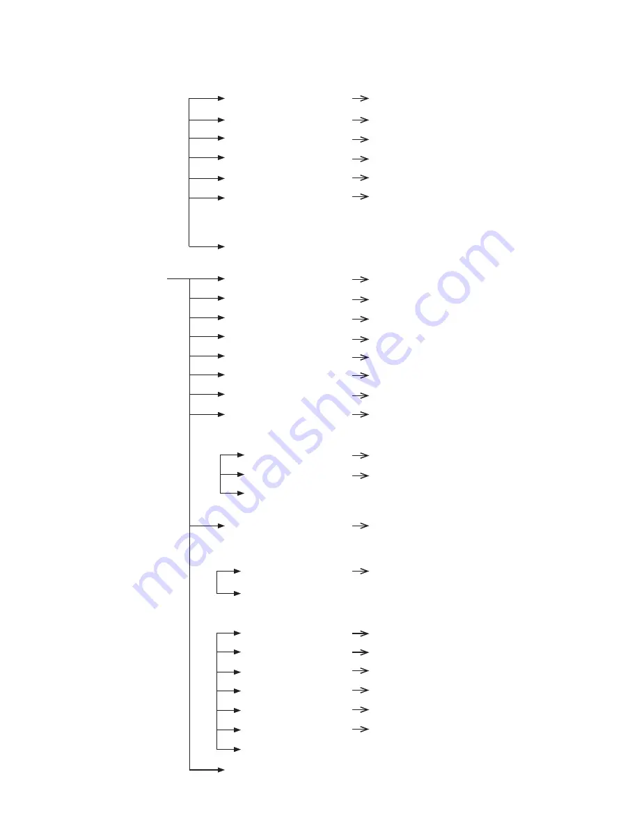
CAMERA 
SET

DAY & NIGHT

MODE

AUTO / DAY / NIGHT

DELAY

5~60 SEC.

THRESHOLD

1~29

GAP

1~5

BURST

ON / OFF

IR LED ANGLE

AUTO / 60.0,57.0, 55.0, 51.0, 
47.0, 40.0, 37.0, 33.0, 28.0, 
23.0, 20.0,15.0,10.0,8.0,6.0

EXIT

SPECIAL

STABILISER

OFF / ON

HR

OFF / 1~7

IMAGE FLIP

OFF / ON

IMAGE MIRROR

OFF / ON

SHARPNESS

0~14

2D-DNR

AUTO, OFF~15

3D-DNR

AUTO, OFF~15

HLC

OFF / ON

ON
LEVEL

LOW / MID / HIGH

CLIP LEVEL

1~7

EXIT

DEFOG

OFF / AUTO / USER

AUTO
AUTO LEVEL

1~10

EXIT

USER

FOG LEVEL

0~15

FOG GAMMA

0~15

STRENGTH

0~64

UVSTRENGTH

0~13

NOISESUP

0~64

EDGE LEVEL

0~15

EXIT

EXIT

Summary of Contents for Raptor II Ruggedized PTZ

Page 1: ...Raptor II Ruggedized PTZ RPT36M SERIES Instruction Manual Version 3 1 Please read this manual carefully before installation and operation of the product ...

Page 2: ...Mounting Changing the Wiper 14 Pin Cable Connection 5 TELEMETRY CONTROL 11 On Board Protocols DIL Dual In Line Switches Protocol Settings Baud Rate Settings RS485 Address Settings RS485 Termination Keyboard Operation 6 SETUP MENU OVERVIEW 16 MAIN MENU 21 PAN TILT SET ID DISPLAY P T DISPLAY CAMERA NAME MANUAL SPEED PROPO P T DIGITAL FLIP IMAGE HOLD INSTALLATION AUTO REFRESH EXIT ...

Page 3: ...EQ SET PRESET TOUR SCAN PATTERN AUTO PAN AUTO RUN HOME POSITION EXIT ZONE SET AREA SEL AREA DEFINE AREA COLOUR AREA NEW SET HEIGHT EDIT WIDTH EDIT PAN ANGLE TILT ANGLE EXIT ALARM SET ALARM DISPLAY ALARM IN ALARM OUT TIME OUT EXIT WIPER SET WIPER RUN EXIT INITIALISE SET POWER ON RESET PAN TILT INIT CAMERA INIT AUTO SEQ INIT PRIVACY ZONE INIT FACTORY INIT EXIT ...

Page 4: ...of the camera The angle of LED coverage goes from 60 degrees at its widest part to 6 degree at its narrowest This minimises light pollution and eliminates IR illumination of unimportant areas Medium to long range targets become the true focal point for the camera lens and the LED s There is also a built in and adjustable de fog function which enhances images in foggy or misty environments Features...

Page 5: ...y can cause abnormal heat generation or fire 4 Securely plug or connect the power cord into the power receptacle An insecure or loose connection may cause a fire 5 When installing the camera on a wall or ceiling etc fasten it securely using suitable anchor bolts and or fixings An unsecured camera could fall and cause serious personal injury or even a fatality 6 Do not place conductive objects e g ...

Page 6: ...diators 4 If an already installed product needs to be relocated make sure the power is turned off before it is moved 5 Always try and install in a well ventilated environment 6 Make sure the camera is adequately protected against lightning strikes by using a suitably rated surge protector which must be locally grounded Failure to do so could irreparably damage the camera and any attached communica...

Page 7: ... Genie Raptor ManualVer 3 1 Edition GN April 2013 Please put the supplied anticorrosive silicon grease over the edge area on each screw hole of the PCD adapter plate before using M8 Hex Bolts Instruction ...

Page 8: ...which comply with the industrial standard 4 142 0mm PCD Cable connections are made using the camera base The camera base is supplied with a 4 142 0mm PCD adapter plate and connects to a bracket or tower using three M8 Hex Bolts s w p w and Nylon Nuts with Spring and Plate Washers Mounting Options UK Column Mounting The camera is supplied with an adapter 4 101 6mm PCD which complies with the unifor...

Page 9: ...ster Keylock Cog failure to do so will result in irreparable damage to the camera head After tilting down the camera module to the required angle replace the Master Keylock Cog this is keyed and only can be located in a unique position the M3 Retaining Screws and the Hex Bolt The Torque setting for the Hex Bolt is 0 84Kg m A Safety Wire made from stainless steel is provided for securing the Raptor...

Page 10: ...xial based video transmission equipment Some limitation on protocols and or software changes may not guarantee to take full advantage of all the features from the manufacturer and may limit features and operation of the Raptor When the Telemetry Control is based on RS485 the address range is limited to 127 Please keep the window glass clean to maintain clear images The Wiper can be removed changed...

Page 11: ...Board Protocols including BBV 422 Pelco D Pelco P DIL Dual In Line Switches Two 8 way DIL Switches are contained within a waterproofed cover on the camera body these are used to select the camera address communication protocol and baud rate Cover Retained by Four Screws Screws and Cover Removed ...

Page 12: ...o you can leave the Address as 0 Baud Rate Settings The Baud Rate communication speed is selected using switches DP21 5 DP21 6 and DP21 7 Baud Rate configuration settings are as follows Description No DP21 1 DP21 2 DP21 3 DP21 4 Apply PELCO D 0 OFF OFF OFF OFF OK PELCO P 1 ON OFF OFF OFF OK BBV 2 OFF ON OFF OFF OK VCL 3 ON ON OFF OFF OK PANASONIC 4 OFF OFF ON OFF OK AD 5 ON OFF ON OFF OK HONEYWELL...

Page 13: ...010110 53 0111000 14 0100010 34 0110110 54 1111000 15 1100010 35 1110110 55 0000100 16 0010010 36 0001110 56 1000100 17 1010010 37 1001110 57 0100100 18 0110010 38 0101110 58 1100100 19 1110010 39 1101110 59 0010100 20 0001010 40 0011110 60 1011110 61 0010101 84 1101011 107 0111110 62 1010101 85 0011011 108 1111110 63 0110101 86 1011011 109 0000001 64 1110101 87 0111011 110 1000001 65 0001101 88 1...

Page 14: ...section Any cable type which exceeds the specification of EIA RS485 can be used The furthest device by cable length should be terminated in accordance with the specification Other devices should remain un terminated see Figure 11 below Keyboard Operation Key Sequences and Joystick movements are executed to closely control the camera and program the Telemetry Control system of Raptor II Examples of...

Page 15: ...ET ID DISPLAY ON OFF P T DISPLAY OFF ON CAM NAME OFF ON MANUAL SPEED 10 110 SEC PROPO P T ON OFF DIGITAL FLIP ON OFF IMAGE HOLD OFF ON INSTALLATION NORMAL INVERT AUTO REFRESH 5 240 EXIT CAMERA SET WDR WDR MODE OFF ON WDR LEVEL 1 7 ATR LEVEL LOW MID HIGH EXIT MD MD DEFINE OFF ON MD DISPLAY OFF ON SENSITIVITY 1 25 INTERVAL T 1 SECOND 4 MINUTES AREA START H 0 XX AREA START V 0 XX AREA END H XX 12 ARE...

Page 16: ...D 0 255 MANUAL BLUE 0 255 EXIT FOCUS ZOOM FOCUS MODE AUTO ZOOMTG MANUAL ZOOM AF SENSITIVE NORMAL LOW DIG ZOOM OFF ON ZOOM SPEED 1 8 ZOOM RATIO ON OFF AF LIMIT BW ON OFF EXIT AE AE MODE AUTO SHUTTER MANUAL IRIS CLOSE F1 6 GAIN 0 15 BRIGHTNESS 1 15 SHUTTER 1 50 1 100000 SLOW SHUTTER OFF ON FLICKERLESS OFF ON BLC OFF ON L LUMINANCE OFF ON EXIT ...

Page 17: ...0 40 0 37 0 33 0 28 0 23 0 20 0 15 0 10 0 8 0 6 0 EXIT SPECIAL STABILISER OFF ON HR OFF 1 7 IMAGE FLIP OFF ON IMAGE MIRROR OFF ON SHARPNESS 0 14 2D DNR AUTO OFF 15 3D DNR AUTO OFF 15 HLC OFF ON ON LEVEL LOW MID HIGH CLIP LEVEL 1 7 EXIT DEFOG OFF AUTO USER AUTO AUTO LEVEL 1 10 EXIT USER FOG LEVEL 0 15 FOG GAMMA 0 15 STRENGTH 0 64 UVSTRENGTH 0 13 NOISESUP 0 64 EDGE LEVEL 0 15 EXIT EXIT ...

Page 18: ...ATW SET EXIT TOUR SET TOUR NO 1 5 TOUR NO DEF OFF ON NAME TOURGROUP 1 TOUR NAME DEF OFF ON DWELL TIME 1 120 EXIT SCAN SCAN NO 1 5 SCAN DEFINE OFF ON NAME SCANGROUP 1 SCAN NAME DEFINE OFF ON PAN START POS 180 PAN END POS 350 TILT POS 45 SCAN SPEED 2 5 10 20 S EXIT PATTERN PATT NUMBER 1 2 PATT DEFINE OFF ON NAME PATTERN001 PATT NAME DEF OFF ON PATT RECORD OFF ON PATT SPEED 2 5 10 20 S EXIT ...

Page 19: ...XIT ZONE SET AREA SELECT 1 8 AREA DEFINE OFF ON AREA COLOUR BLACK MOSAIC AREA NEW SET OFF ON HEIGHT EDIT XXX WIDTH EDIT XXX PAN ANGLE XXX TILT ANGLE XXX EXIT ALARM SET ALARM DISPLAY OFF ON ALARM IN SET ALARM OUT OFF ON TIME OUT 1 10 SECONDS EXIT WIPER SET WIPER RUN AUTO PUSH RUN STOP EXIT INITALISE SET POWER ON RESET PAN TILT INIT CAMERA INIT AUTOSEQ INIT PRIVACY ZONE INIT FACTORY INIT EXIT ...

Page 20: ...mera to tailor it to their personal needs Selection UP DOWN LEFT RIGHT KEYS Menu Open IRIS OPEN KEY Menu Close IRIS CLOSE KEY MAIN MENU 1 PAN TILT SET 2 CAMERA SET 3 AUTOSEQ SET 4 ZONE SET 5 ALARM SET 6 WIPER SET 7 INITIALISE SET 8 EXIT 1 PAN TILT SET 1 ID DISPLAY ON OFF 2 P T DISPLAY ON OFF 3 CAMERA NAME OFF ON 4 MANUAL SPEED 10 110 SECOND 5 PROPO P T ON OFF 6 DIGITAL FLIP ON OFF 7 IMAGE HOLD OFF...

Page 21: ...AME DISPLAY is set to ON MANUAL SPEED Adjustable maximum speed when PAN TILT are manually controlled PROPO P T Automatically adjusts the PAN TILT movement speed according to the Zoom magnification level OFF PAN TILT movement is not automatically controlled ON The PAN TILT speed slows down on higher zoom magnification AUTO FLIP OFF Operates when TILT is below 90 ON Operates when TILT is over 90 IMA...

Page 22: ... after setting a zone Selection UP DOWN LEFT RIGHT KEYS Menu Open IRIS OPEN KEY Menu Close IRIS CLOSE KEY 1 1 1 DISPLAY ID location can be changed as follows 1 Select ON from ID DISPLAY 2 Press IRIS OPEN KEY MOVE U D L R EXIT IRIS CLOSE 1 2 CAMERA NAME DISPLAY CAMERA NAME MAINCAMERA 0123456789ABCDEFGH IJKLMNOPQRSTUVWXYZ DELETE IRISOPEN POSITION IRISOPEN EXIT Selection UP DOWN LEFT RIGHT KEYS Menu ...

Page 23: ... name select POSITION and press the IRIS OPEN KEY The method for changing the position of the camera name is the same as in ID DISPLAY WDR MODE OFF WDR doesn t work ON WDR is activated WDR LEVEL Adjusts the brightness when WDR is activated ATR LEVEL Adjusts the contrast in dark areas 2 CAMERA SET 1 WDR 2 MOTION DET 3 ATW 4 FOCUS ZOOM 5 AE 6 DAY NIGHT 7 SPECIAL 8 EXIT 2 1 WDR SETUP 1 WDR MODE OFF O...

Page 24: ...a for Motion Detection AREA END H AREA END V Set an end area for Motion Detection Caution 1 Motion Detection doesn t work in SCAN PATTERN settings 2 When using MD the DWELL TIME should be a minimum of 3 seconds in TOUR settings 3 Do not set MD if an unstable light source is present e g flickering light 4 Instant changes in light sources may cause false activations e g turning lights on or off 5 Th...

Page 25: ...atically compensated ATW MODE ATW White Balance is automatically compensated when the colour temperature range is 2500 K 9500 K ATW MODE OUTDOOR White Balance is optimised for an outdoor environment ATW MODE INDOOR White Balance is optimised for an indoor environment ATW MODE ONE PUSH White Balance is optimised for the current lighting conditions If the lighting conditions change the White Balance...

Page 26: ...tomatically MANUAL FOCUS is adjustable manually ZOOMTG Whenever ZOOM changes the FOCUS also changes AF SENSITIVE NORMAL Focus is adjusted normally LOW Drop the Auto Focus sensitivity to reduce the number of AF operations DIG ZOOM Digital Zoom activates at the maximum level of the Optical Zoom if the user keeps pushing the Tele button ZOOM SPEED Adjusts the zoom tracking speed ZOOM RATIO Displays t...

Page 27: ... around the screen edges may not be properly in focus If the IR LED s are ON and the Zoom Ratio is over 20x the focus mode will be set to manual regardless of the focus mode settings in order to stabilise the focus OFF AF operates with the FOCUS MODE set in the FOCUS ZOOM MENU on the OSD ON This function is useful when IR LED s are ON and Zoom Ratio goes over 20x FOCUS MODE changes to MANUAL in th...

Page 28: ...up or down to get improved image quality SLOW SHUTTER When AE MODE is AUTO and the brightness is decreased shutter speed is set automatically OFF AUTO Under low light conditions shutter speed is automatically controlled according to the brightness of the scene ON MANUAL Under low light conditions shutter speed is controlled according to a set point BLC This function is useful if the subject shows ...

Page 29: ... Colour to B W A higher threshold value makes an earlier change from Day to Night at lower AGC levels i e In brighter conditions GAP The gap level when switching between Colour to B W mode and B W to Colour mode BURST Output the BURST signal when switching to B W mode IR LED ANGLE AUTO IR LED ANGLE is controlled automatically according to the ZOOM ratio 60 0 IR LED ANGLE is fixed at 60 degrees 6 0...

Page 30: ...ubject to movement HR Horizontal resolution in Colour mode is 700 TV Lines Users can increase the HR up to 750TVL by adjusting the level in BW mode But if the level is set too high in B W mode it can make create image noise and or edge distortion IMAGE FLIP The image is flipped vertically IMAGE MIRROR The image is flipped horizontally SHARPNESS Overall sharpness on the screen is adjustable 2D DNR ...

Page 31: ...G AUTO Automatically start the DE FOG function USER USER Setting The higher the value set for the AUTO LEVEL DEFOG function the greater the sensitivity FOG LEVEL Fog Density FOG GAMMA The adjustable numeric value for contrast level control STRENGTH If this value is high bright parts of the image get darker and dark parts get brighter 2 7 1 DEFOG AUTO SETUP 1 AUTO LEVEL 0 10 2 EXIT 2 7 2 DEFOG DEFO...

Page 32: ...ched ON Menu Shift UP DOWN LEFT RIGHT KEYS Menu Open IRIS OPEN KEY Menu Close IRIS CLOSE KEY PRESET Locations for the PAN TILT and ZOOM functions can be programmed In an ALARM or TOUR operation the camera moves to the programmed preset SEQ The programmed PRESETS are executed sequentially from the lowest number TOUR PRESET works in GROUP Up to 5 Presets per Group can be registered and up to 5 Group...

Page 33: ...ATT A PAN Are executed automatically after the user exits the OSD MENU HOMEPOSITION If there is any loss of power the camera goes to this programmed Preset If AUTORUN is set the camera does not go to the programmed Preset Menu Shift UP DOWN LEFT RIGHT KEYS Menu Open IRIS OPEN KEY Menu Close IRIS CLOSE KEY 3 1 PRESET This function after programming moves the camera to a designated position 1 PRESET...

Page 34: ...ting use the shortcut keys shown below 67 GO PRESET AUTO 68 GO PRESET MANUAL PRESET NAME OFF When using a PRESET the PRESET name is not displayed on the screen ON When using a PRESET the PRESET name is displayed on the screen Default for PRESET name is PRESET001 and the editing method is as follows 1 After changing a PRESET NAME from OFF to ON press the IRIS OPEN KEY 2 Editing a PRESET NAME is the...

Page 35: ...on 2 3 ATW Caution When setting a PRESET and TILT is over 90 PAN TILT automatically moves to the position 20 90 and TILT is limited to 90 TOUR NO A maximum of 5 groups can be registered TOUR NO DEF OFF TOUR Group setting is cancelled ON TOUR is set up 3 2 TOUR This function makes the camera repeatedly follow a series of pre programmed presets 1 TOUR NO 1 5 2 TOUR NO DEF OFF ON 3 NAME TOURGROUP1 4 ...

Page 36: ...rst change TOUR NAME DEF from OFF to ON then press the IRIS OPEN KEY 2 Changing a Tour Group name uses the same method shown in 1 3 CAMERA NAME DISPLAY DWELL TIME Is the waiting time between a PRESET execution and moving to the next PRESET Caution If TOUR GOURP1 PRESET is set up as follows After moving through PRESET1 PRESET2 PRESET3 the camera returns to PRESET1 If any PRESET is OFF during an ope...

Page 37: ... in AUTO RUN Setting Example SCAN will be executed in programmed preset 1 3 5 The method for setting up SCAN1 in PRESET is as follows 1 Register 1 as the SCAN NO 2 Change SCAN DEFINE from OFF to ON and press the IRIS OPEN KEY NAME This changes the SCAN Name The method for changing the SCAN NAME is as follows 1 Change SCAN NAME DEF from OFF to ON and press the IRIS OPEN KEY 2 The method for changin...

Page 38: ...thod for setting up PAN END POS is the same as for PAN START POS TILT POS This sets up the TILT angle in the SCAN Set up is similar to PAN START POS but the UP DOWN keys should be used SCAN SPEED Sets up the SCAN Speed The speed can be set between 2 second slow 20 second fast Caution 1 The values applied for WDR and ATW are those set on the OSD 2 Set up angles of the initial and end location for t...

Page 39: ...D from OFF to ON and press the IRIS OPEN KEY PAN TILT Shift UP DOWN LEFT RIGHT 2 Move PAN TILT to the desired position before starting PATTERN 3 Press the IRIS OPEN KEY to start the process 4 Press the IRIS CLOSE to save the process Caution 1 If there is no PAN TILT movement no PATTERN is memorised 2 The values applied for WDR and ATW are those set on the OSD 3 If a PATTERN is set with a TILT angl...

Page 40: ...IS CLOSE KEY For Privacy protection use and set MOSAIC ZONE AREA SEL Up to 8 PRIVACY ZONES can be defined AREA DEFINE OFF PRIVACY ZONE is not activated ON PRIVACY ZONE is activated AREA COLOUR The colour of the MOSAIC ZONE is selectable AREA NEW SET OFF Previous PRVIACY ZONE is activated ON New PRIVACY ZONE is set up from the current PAN TILT position when switching from OFF to ON the PRIVACY ZONE...

Page 41: ...ss the IRIS OPEN KEY again 3 Change AREA SEL to 1 4 Change AREA DEFINE from OFF to ON 5 Change AREA NEW SET from OFF to ON 6 New ZONE is activated in the centre of the screen and the ZONE can be moved using the HEIGHT WIDTH PAN and TILT Menu 7 Press the IRIS CLOSE KEY to finalise the set up Caution Please set a MASK within 20 80 of the TILT angle If a MASK is set at a TILT angle over 90 PAN TILT a...

Page 42: ...om PRESET to the reactivation of a TOUR after an ALARM IN has been received Caution 1 PRESET DEFINE must be set to ON to activate ALARM IN 2 A ground signal from an external alarm must be maintained for a minimum of 200ms 6 WIPER SET AUTO WIPER is activated at TILT angle within 80 100 PUSH WIPER is activated once RUN WIPER ON STOP WIPER OFF Select the menu using the Joystick and press the IRIS OPE...

Page 43: ...ised CAMERA INIT Only the CAMERA setting menu is initialised AUTO SEQ INIT 1 Only the AUTO SEQ menu is initialised 2 PRESET information and PATTERN memory are not initialised PRIVACY ZONE INIT PRIVACY ZONE is initialised FACTORY INIT All Menu set ups are reset to factory defaults WTX 1200A Simple PRESET Setting The following keyboard controller can be used for camera commands when the OSD MENU is ...

Page 44: ...SD Menu WTX 1200A Simple PRESET Shift Press the PRESET number followed by the F1 key and the camera moves to the corresponding PRESET position However this is only valid up to PRESET no 32 for which PRESET DEFINE is set to ON WTX 1200A Simple TOUR Operation Press number 71 on the keypad followed by the F1 key This works when TOUR DEFINE is ON and the TOUR related MENU is properly set up WTX 1200A ...

Page 45: ...ow to operate SUB MENU 95 GO PRESET MENU KEY or Press IRIS OPEN How to operate MAIN EXIT 1 Move to EXIT and Press MENU KEY or IRIS OPEN 2 Press IRIS CLOSE or 96 GO PRESET Number Function 1 64 Preset Setting Preset Press Preset button for more than 2 seconds 1 64 Preset Executing Preset 65 Preset Executing A PAN 66 Preset Executing Scan 70 Preset Executing Sequency 71 Preset Executing Tour 81 Prese...

Page 46: ......

Page 47: ...47 Genie Raptor ManualVer 3 1 Edition GN April 2013 Dimensions mm ...

Page 48: ... Raptor ManualVer 3 1 48 Edition GN April 2013 CCTV House City Park Watchmead Welwyn Garden City Hertfordshire AL7 1LT Tel 44 0 1707 330541 Fax 44 0 1707 330543 Mail marketing geniecctv com www geniecctv com ...

Reviews: