- 18 -
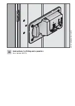
Fitting the cylinder
1. Remove the front plate.
2. Remove the screws (1- 4 screws) holding the top
cover to the enclosure.
3. Push the cylinder into the top cover from the inside
until the threaded hole in the cylinder is in line with
the hole in the top cover. Secure the cylinder to the
top cover with the M 5 type screw provided.
4. Put the key in the cylinder and turn it until the lug is in
line with the slot in the internal security plate. Push
the top cover and the base together and refit the
screws. Refit the front plate.
THE TOP COVER CAN ONLY BE REMOVED IF YOU
HAVE THE RIGHT KEY
Installation instructions for the KABA or KESO-Lips
cylinders
You can only use those cylinders that have a lug which
can be set in 8 different positions. To use these type of cy-
linders the switchbox has to be modified and a special
electrical contact fitted in our factory. If you have one of
these contacts, please follow the installation
instructions on the next page.
Montagehandleiding voor de half-
profielcilinder (conform DIN 18252)
In principe kunt u alle in de handel verkrijgbare DIN
halfprofilcilinders gebruiken. Standaard hebben deze
cilinders een 8 - voudige verstelbare baard die u, afhan-
gelijk van het schakelaartype, kunt verstellen op
90° links
,
90° rechts
of
0° (12 uur)
.
Laast u zich door uw sloten leverancier adviseren of
bestel de benodigde cilinder gelijk mee met de sleutel-
schakelaar.
In principe moet de verstelbare baard van de cilinder
op 90° links zijn ingesteld, alleen bij de schakelaar
types 1-1 R moet de verstelbare baard in de posltie
90° rechts zijn ingesteld.
Bij de miniatuur schakelaars is de positie van de
baard O° (12 uur) !!!!!
1. Venwijder de Aluminiumrozet of frontpiaat van
de schakelaar.
2. Verwijder het deksel van de schakelaar, afhankelijk
van het type 1 tot 4 boutjes.
NL
Summary of Contents for GDT 1
Page 2: ...2 Schalteinsatz ES 2T R 2...
Page 3: ...3...
Page 11: ...11...
Page 12: ...12 Schalteins tze J J 1T 1 J 2T 1 J 1T 2 J 2R 2 J 1TR 2 J 1R 2...
Page 14: ...14...


