GEA XKR Operating Instructions Manual Download Page 16

14

2014-10 · Flow Diversion Device with Proximity switch

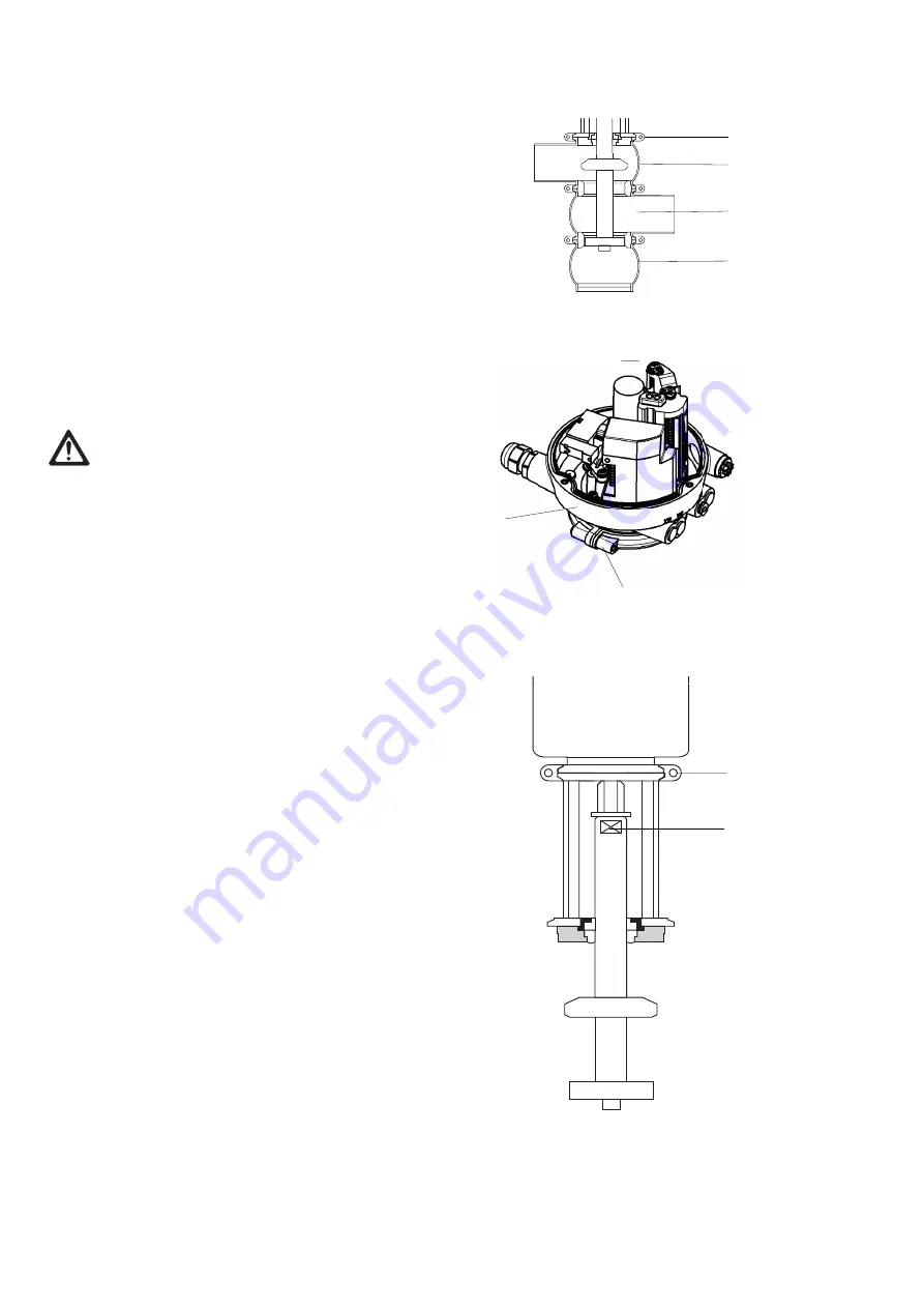
Disassembly the control module

• Remove the hinged clamps (1).

Lower the valve disk :
• Depressurize the actuator. 

The pneumatic and electrical connections can remain
connected to the control module.

• Remove the hinged clamps (5) between the control

module and the actuator.

• Lift the control module (6) upwards.

Disassembly the valve insert

CAUTION

When pulling out the valve do not damage the valve
seat.
Do not set the valve insert down on the valve disk, as
this can damage the valve disk, but lay it down
carefully. 

•Pull the valve out of the housing (2, 3, 4).

Loosen the valve disk

• Slacken the hinged clamps (7) between the actuator

and the lantern. 

• Grip the valve disk at the key face (8) with an open-

end spanner, turn the actuator 3 turns using a strap
wrench. The valve disk will come loose.

1

2

3

4

8

7

5

6

Summary of Contents for XKR

Page 1: ...XKR XWR Issue 2014 10 Revision 15 Part no 430 455 English Operating Instructions Flow Diversion Device with Proximity Switch ...

Page 2: ...2014 10 Flow Diversion Device with Proximity switch ...

Page 3: ... position 9 Valve with detachable housing connections 9 Valve with welded connections 9 Pneumatic connections 10 Electrical connections 10 Hosing diagram 11 Commissioning 12 Malfunction Cause Remedy 12 Maintenance 12 Inspections 12 Maintenance intervals 1 Prior to disassembly the valve 13 Disassembly of Flow Diversion Device 13 Maintenance 15 Assembling 17 Dual Stem Device Test Procedures 19 Techn...

Page 4: ...sure for volume cubic decimetre Volume litre under standard conditions DN DIN nominal width DIN Deutsche Norm German standard DIN Deutsches Institut für Normung e V German institut for Standardization EN European standard EPDM Material designation Short designation acc to DIN ISO 1629 Ethylene propylene diene monomer rubber GEA GEA AG group of companies GEA stands for Global Engineering Alliance F...

Page 5: ...ions or conversions which affect the safety of the Flow diversion device are not permitted Safety devices must not be bypassed removed or made inactive Only use original spare parts and accessories recom mended by the manufacturer General instructions The user is obliged to operate the Flow diversion device only when it is in good working order In addition to the instructions given in the operatin...

Page 6: ...on actuated valve spring closing action are detached there is danger of injury since the released spring pressure suddenly lifts the actuator 5 Therefore prior to detaching the hinged clamps release the spring tension by the pneumatic emergency switchbar or pressurizing the actuator with compressed air CAUTION Housing sockets have very sharp edges Therefore wear suitable protection gloves during t...

Page 7: ...pp 20 OD 1 1 2 app 18 app 36 OD 2 app 18 app 36 OD 2 1 2 app 25 app 50 OD 3 app 25 app 50 OD 4 app 26 app 52 OD 6 app 82 app 164 Transport DANGER For transport of the package only use suitable lifting gear and slings Observe the instruction symbols on the package and on the Flow diversion device Handle the Flow diversion device with care to avoid damage caused by shock or careless unloading The sy...

Page 8: ...isk X 2 11 valve housing 12 bearing 13 bearing disk 14 seat ring 15 pneumatic connection For housing configura tions see the spare parts drawings 1 4 5 6 7 11 12 13 14 15 8 9 10 2 10 1 2014 10 Flow Diversion Device with Proximity switch 6 Divert Valve Leak Detect Valve Inlet Port Divert Port to Balance Tank Leak Detection Port to Balance Tank Forward Flow Port ...

Page 9: ...eriods of sub legal pasteurization temperatures The valve position is detected by a sensors installed in the control module The interface module with two sen sors to determine the valve position is installed in the control module The sensors determine the valve posi tion and the interface module generate the correspond ing feedback signals and send them to the master con trol system see operating ...

Page 10: ...etect position the Divert Valve is in the activated position The Leak Detect Valve is in the closed position which is detected by the sensor in the control module The Flow Diversion Device will stay in the Leak Detect position until the Flow Diversion Device Con troller sends out the signal to transition to the Forward Flow position Forward Flow position The Forward Flow position enables the paste...

Page 11: ...secure the pipe against incoming product Valves with detachable housing connections can be in stalled directly into the pipe system if suitable connec tion fittings are used Valve with welded connections CAUTION For welding operations all internals must be removed from the valve housing 1 DANGER When the hinged clamps at the actuator or at the hous ing of the non actuated divert valve X spring clo...

Page 12: ... 1 212 2 00 T 1 212 3 10 T 61 212 4 00 U 61 261 5 10 1 Actuators with booster cylinder for increasing the pneumatic actuat ing force when lower control air pressures are used Installing the air hose To ensure optimum fit in the air connector the pneumatichosesmust be cut square with a hose cutter Shut off the compressed air supply Push the air hose into the air connector port P in the control modu...

Page 13: ... in the air connec tor the pneumatic hoses must be cut square with a hose cutter Hosing Diagram Flow Diversion Device FDD GEA Tuchenhagen Datum date 2009 06 26 A View A FDD P with solenoid FDD N without solenoid Y1 Central Air Supply Central Air Supply Outlet P P Central Air Supply P Actuator ...

Page 14: ...ctive solenoid valve Valve does Dirt foreign Clean the valve not close materials between housing and valve seat and the valve seat valve disk Valve closes O rings dry Grease the O rings too slowly in the actuator and in the control module friction losses Leakage at the O rings in the Dismantle the valve housing housing valve housing defective replace the O rings Leakage in the Sealing ring Replace...

Page 15: ...intenance and repair work no process is in operation in the area concerned All pipe system elements attached to the Flow diver sion device must be drained and if necessary cleaned or rinsed Shut off the control air supply unless it is required for disassembly the Flow diversion device Disconnect the power supply If possible take the valve out of the pipe system togeth er with all housings and hous...

Page 16: ...ft the control module 6 upwards Disassembly the valve insert CAUTION When pulling out the valve do not damage the valve seat Do not set the valve insert down on the valve disk as this can damage the valve disk but lay it down carefully Pull the valve out of the housing 2 3 4 Loosen the valve disk Slacken the hinged clamps 7 between the actuator and the lantern Grip the valve disk at the key face 8...

Page 17: ...Maintenance CAUTION The stem of the valve disk 3 the housing seat 4 the valve seat 6 and the V ring groove 5 are precision parts which must not be damaged Dismantle the Flow diversion device see Chapter Disassembly Carefully clean the individual components CAUTION Observe the safety information sheets issued by the detergent manufacturers Only use detergents which are non abrasive and non aggressi...

Page 18: ...ter with household washing up liquid 1 drop 1 l as an aid to inserting V rings In order to prevent oxidation from infiltration prepare the liquid solution in a ceramic plastic or stainless steel container Before inserting the V ring wet it on the back side not in contact with the product Take care that there is no water in the V ring groove in the valve disk CAUTION Observe the required installati...

Page 19: ...a F L G MD 2 under part no 413 071 CAUTION When mounting the control module make sure that the air hoses do not get kinked Assembling Mounting to The control module T VIS onto FDD CAUTION The permanent magnet on the switch bar 1 is fragile and must therefore be protected against mechanical impact stress The magnetic fields can delete data carriers and affect or destroy mechanical components Check ...

Page 20: ...the spacer nut 2 against the actuator rod 1 Tighten the nuts of the clamps at the control module with a torque of 1 Nm Tighten the nuts of the hinged clamps with following torques M 6 9 Nm M 8 22 Nm Tighten the nuts of the cast semi annular clamps with a torque of 45 Nm 33 lbft Checking the valve stroke Actuate the valve by applying compressed air Check whether the valve stroke c is correct Valve ...

Page 21: ...ches from the Lock Nut using the Spacer provided to set the gap accurately see figure B Lock the Limit Test Stop in place with the Lock Nut Activate the valve to Divert Flow Position The metering pump or any other flow promoting device should not start See Corrective Action if the metering pump does not respond as indicated After test Set the valve to Forward Flow Position Slacken the lock nut and...

Page 22: ...d arranges for proper disposal free of charge Technical Data Size 1 to 6 OD Weight 20 to 164 kg depending on size and equipment Material of product stainless steel 1 4404 contact parts Check corrosion resistance with respect to media and detergents Installation position any position if valve and pipe system can drain properly Ambient temperature 0 45 C standard Valve 0 C use control air with low d...

Page 23: ...C 10 200 C 25 140 C caustics at 2 5 up to 80 C up to 40 C conditionally resistant strong caustics sufficiently resistant not resistant not resistance acids at 2 5 up to 80 C up to 100 C conditionally resistant strong acids not resistant not resistant not resistance saturated steam up to 135 C resistant conditionally resistant resistant fuels hydrocarbons not resistant conditionally resistant not r...

Page 24: ...ty switch Date 2014 10 13 Page 1 of 2 221ELI007089E_2 DOC Spare parts list Flow Diversion Device with T VIS M 1 FDD 43 45 B A 10 9 2 43 45 5 1 15 5 5 5 5 43 45 94 117 6 Z 5 5 5 5 5 43 45 43 45 15 1 2 9 94 A B 33 33 7 3 33 4 4 3 7 117 6 10 43 45 33 ...

Page 25: ... 09 221 121 22 10 Limit stop cpl 1 4404 1 4301 221 156 13 221 156 13 221 156 13 221 156 01 221 156 01 221 156 01 221 156 06 15 Valve disk X_R 1 4404 221 700 06 221 700 05 221 700 04 221 700 03 221 700 01 221 700 02 221 700 07 33 Seat ring X_R 1 4404 221 699 04 221 699 03 221 699 03 221 699 01 221 699 01 221 699 02 221 699 05 35 Blanking plate 1 4404 221 144 01 221 144 02 221 144 02 221 144 03 221 ...

Page 26: ...29 50 570 15 1 OD 38 1x1 6 59 90 135 45 180 360 465 5 36 5 39 60 615 23 2 OD 50 8x1 6 71 5 90 135 45 180 360 472 43 42 65 650 30 2 OD 63 5x1 6 90 125 170 80 250 500 515 52 54 75 740 30 3 OD 76 2x1 6 103 125 170 80 250 500 521 5 58 5 54 80 780 30 4 OD 101 6x2 127 5 125 210 40 250 500 530 71 69 95 850 30 6 OD 152 4x2 77 177 150 260 40 300 600 707 95 5 94 120 1150 60 P clearance required for maintena...

Page 27: ...25 2014 10 Flow Diversion Device with Proximity switch ...

Page 28: ...I006048E Spare parts list Control Module T VIS M 1 FDD GEA Tuchenhagen GmbH 7 53 21 39 24 15 26 65 FDD N 63 FDD P 8 56 48 5 1 1 1 39 15 55 47 57 22 54 31 52 57 57 43 66 42 Ø2 Detail X for lead wire seal X Type FDD N Control Module without solenoid valve Type FDD P Control Module with solenoid valve 26 1 26 2 ...

Page 29: ... gland PA 508 299 508 299 508 299 508 299 26 Sound absorber Ms vern 933 967 933 967 933 967 933 967 31 O ring NBR 930 041 930 041 930 041 930 041 39 Cheese head screw A2 70 902 115 902 115 902 115 902 115 42 O ring NBR 930 436 930 436 930 436 930 436 43 Interface module 221 589 20 221 589 20 221 589 20 221 589 20 47 Adaptermodul AC interface Connection type 20 130V AC Connection at interface modul...

Page 30: ...uchenhagen de We live our values Excellence Passion Integrity Responsibility GEA versity GEA Group is a global engineering company with multi billion euro sales and operations in more than 50 countries Founded in 1881 the company is one of the largest providers of innovative equipment and process technology GEA Group is listed in the STOXX Europe 600 index ...

Reviews: