


13
2014-10 · Flow Diversion Device with Proximity switch
Maintenance intervals
To ensure the highest operational reliability of the
valves, all wearing parts should be replaced at longer
intervals.
The actual maintenance intervals can only be deter-
mined by the plant user, since they depend on the oper-
ating conditions, for instance
– daily period of operation
– switching frequency
– type and temperature of the product
– type and temperature of the cleaning solution
– ambient conditions.
Application
Maintenance interval
(recommendations)
Media at temperatures of
every 3 months
60 °C to 130 °C
Media at temperatures
every 12 months
< 60 °C
Prior to disassembly the
Flow diversion device
DANGER
Before detaching the pipe connection and the semi-
annular clamp connections on the valve housing, always
take the following preparatory measures:
• Make sure that during maintenance and repair work
no process is in operation in the area concerned.
• All pipe system elements attached to the Flow diver-
sion device must be drained and, if necessary, cleaned
or rinsed.
• Shut off the control air supply, unless it is required for
disassembly the Flow diversion device.
• Disconnect the power supply.
• If possible, take the valve out of the pipe system togeth-
er with all housings and housing connections.
Disassembly of Flow
Diversion Device
NOTE
The pneumatic and electrical connections can remain in
the control module.
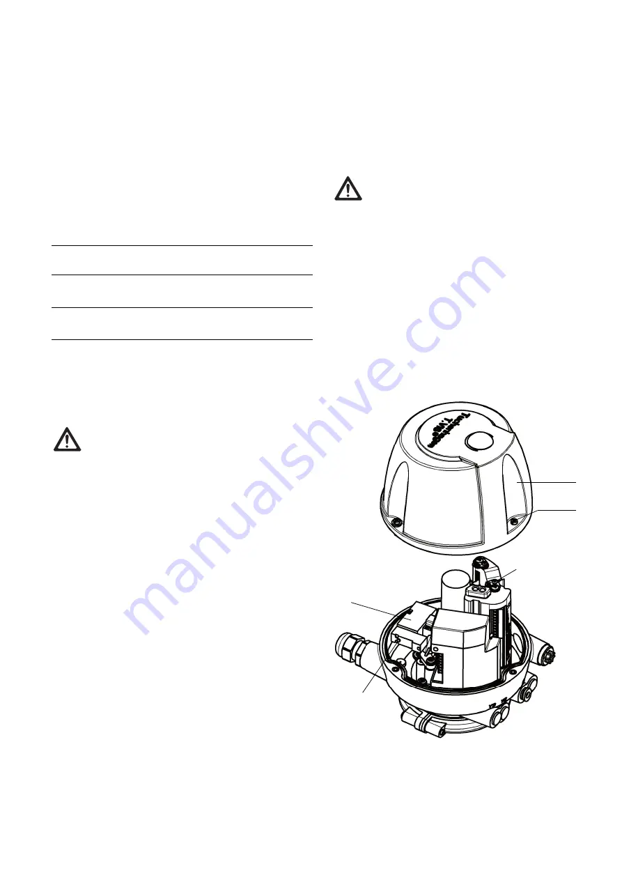
• Loose the cheese head screw (25) and remove cap (B1).
DANGER
When the hinged clamps are detached of the non-actu-
ated valve, the released spring force suddenly lifts the
actuator. There is danger of injury.
Therefore, prior to detaching the hinged clamps, release
the spring tension by actuating the valve actuator with
compressed air.
Lift the valve disk:
Spring-closing valve
• Pressurize the actuator with compressed air,
max. 8 bar by activating solenoid valve Y1 at S.
Spring-opening valve
• Depressurize the actuator.
25
B1
Y1
S