5-52
F35 Multiple Feeder Protection System
GE Multilin
5.2 PRODUCT SETUP
5 SETTINGS
5
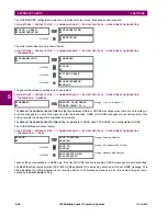
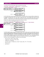
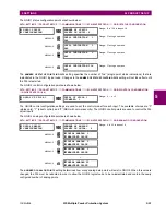
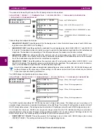
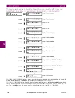
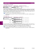
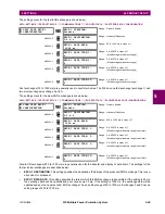
The measured value settings for each of the 32 analog values are shown below.
PATH: SETTINGS
PRODUCT...
COMMUNICATIONS
IEC 61850 PROTOCOL
GGIO4 ANALOG CONFIGURATION
GGIO4 ANALOG 1(32) MEASURED VALUE
These settings are configured as follows.
•
ANALOG IN 1 VALUE
: This setting selects the FlexAnalog value to drive the instantaneous value of each GGIO4 ana-
log status value (GGIO4.MX.AnIn1.instMag.f).
•
ANALOG IN 1 DB
: This setting specifies the deadband for each analog value. Refer to IEC 61850-7-1 and 61850-7-3
for details. The deadband is used to determine when to update the deadbanded magnitude from the instantaneous
magnitude. The deadband is a percentage of the difference between the maximum and minimum values.
•
ANALOG IN 1 MIN
: This setting specifies the minimum value for each analog value. Refer to IEC 61850-7-1 and
61850-7-3 for details. This minimum value is used to determine the deadband. The deadband is used in the determina-
tion of the deadbanded magnitude from the instantaneous magnitude.
•
ANALOG IN 1 MAX
: This setting defines the maximum value for each analog value. Refer to IEC 61850-7-1 and
61850-7-3 for details. This maximum value is used to determine the deadband. The deadband is used in the determi-
nation of the deadbanded magnitude from the instantaneous magnitude.
Note that the
ANALOG IN 1 MIN
and
ANALOG IN 1 MAX
settings are stored as IEEE 754 / IEC 60559 floating point
numbers. Because of the large range of these settings, not all values can be stored. Some values may be rounded
to the closest possible floating point number.
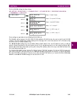
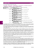
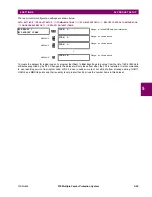
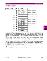
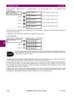
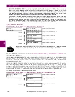
The GGIO5 integer configuration points are shown below:
PATH: SETTINGS
PRODUCT SETUP
COMMUNICATIONS
IEC 61850 PROTOCOL
GGIO5 ANALOG CONFIGURATION
The GGIO5 logical node allows IEC 61850 client access to integer data values. This allows access to as many as 16
unsigned integer value points, associated timestamps, and quality flags. The method of configuration is similar to that of
GGIO1 (binary status values). The settings allow the selection of FlexInteger values for each GGIO5 integer value point.
It is intended that clients use GGIO5 to access generic integer values from the F35. Additional settings are provided to
allow the selection of the number of integer values available in GGIO5 (1 to 16), and to assign FlexInteger values to the
GGIO5 integer inputs. The following setting is available for all GGIO5 configuration points.
•
GGIO5 UINT IN 1 VALUE
: This setting selects the FlexInteger value to drive each GGIO5 integer status value
(GGIO5.ST.UIntIn1). This setting is stored as an 32-bit unsigned integer value.
GGIO4 ANALOG 1
MEASURED VALUE
ANALOG IN 1 VALUE:
Off
Range: any FlexAnalog value
MESSAGE
ANALOG IN 1 DB:
0.000
Range: 0.000 to 100.000 in steps of 0.001
MESSAGE
ANALOG IN 1 MIN:
0.000
Range: –1000000000.000 to 1000000000.000 in steps
of 0.001
MESSAGE
ANALOG IN 1 MAX:
0.000
Range: –1000000000.000 to 1000000000.000 in steps
of 0.001
GGIO5 UINTEGER
CONFIGURATION
GGIO5 UINT In 1:
Off
Range: Off, any FlexInteger
™
parameter
MESSAGE
GGIO5 UINT In 2:
Off
Range: Off, any FlexInteger parameter
MESSAGE
GGIO5 UINT In 3:
Off
Range: Off, any FlexInteger parameter
↓
MESSAGE
GGIO5 UINT 1n 16:
Off
Range: Off, any FlexInteger parameter
NOTE
Summary of Contents for UR F35 Series
Page 10: ...x F35 Multiple Feeder Protection System GE Multilin TABLE OF CONTENTS ...
Page 366: ...5 238 F35 Multiple Feeder Protection System GE Multilin 5 10 TESTING 5 SETTINGS 5 ...
Page 426: ...10 12 F35 Multiple Feeder Protection System GE Multilin 10 6 DISPOSAL 10 MAINTENANCE 10 ...
Page 454: ...A 28 F35 Multiple Feeder Protection System GE Multilin A 1 PARAMETER LISTS APPENDIX A A ...
Page 620: ...F 12 F35 Multiple Feeder Protection System GE Multilin F 2 DNP POINT LISTS APPENDIX F F ...
Page 630: ...H 8 F35 Multiple Feeder Protection System GE Multilin H 3 WARRANTY APPENDIX H H ...
Page 640: ...x F35 Multiple Feeder Protection System GE Multilin INDEX ...

