background image

Chapter 7. Logging Data

138

Transport® Model PT878 Portable Liquid Flowmeter User’s Manual

7.3.1 Setting up a New Log (cont.)

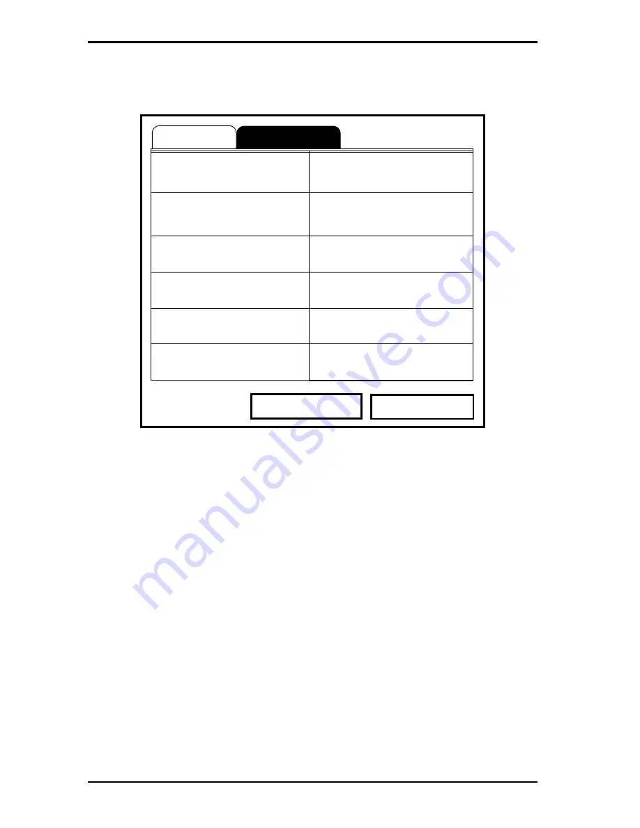
Figure 93: Log Measurements Window

To step through each entry, press the [

T

] key.

1.

Press 

[ENTER]

 to open the first entry. The Select Measurement window 

opens, as shown in Figure 94 on page 139.

General

            Ns

Measurements

NO UNIT                            NO UNIT

Cancel

Activate

NO UNIT                            NO UNIT

NO UNIT                            NO UNIT

NO UNIT                            NO UNIT

NO UNIT                            NO UNIT

NO UNIT                            NO UNIT

Summary of Contents for Transport PT878

Page 1: ...GE Sensing Inspection Technologies Flow 910 219 Rev F November 2009 TransPort Model PT878 Portable Liquid Flowmeter User s Manual ...

Page 2: ......

Page 3: ...2009 General Electric Company All rights reserved Technical content subject to change without notice GE Sensing Inspection Technologies TransPort Model PT878 Portable Liquid Flowmeter User s Manual 910 219 Rev F November 2009 ...

Page 4: ...ii no content intended for this page proceed to next page ...

Page 5: ...hese instructions carefully may cause unreliable performance Caution paragraphs provide information that alerts the operator to a hazardous situation that can cause damage to property or equipment Warning paragraphs provide information that alerts the operator to a hazardous situation that can cause injury to personnel Cautionary information is also included when applicable Safety Issues WARNING I...

Page 6: ...er the work envelope of this equipment during manual operation If you do serious injury can result WARNING Make sure that power to the auxiliary equipment is turned OFF and locked out before you perform maintenance procedures on the equipment Qualification of Personnel Make sure that all personnel have manufacturer approved training applicable to the auxiliary equipment Personal Safety Equipment M...

Page 7: ...es that could impact health and the environment In order to avoid the dissemination of those substances in our environment and to diminish the pressure on the natural resources we encourage you to use the appropriate take back systems Those systems will reuse or recycle most of the materials of your end life equipment in a sound way The crossed out wheeled bin symbol invites you to use those syste...

Page 8: ...Preface vi Transport Model PT878 Portable Liquid Flowmeter User s Manual no content intended for this page proceed to next page ...

Page 9: ...al Setup 2 1 Making Electrical Connections 6 2 1 1 Power Connections 7 2 1 2 Transducer Connections 7 2 1 3 Input Output Connections 7 2 1 4 The Infrared Wireless Interface 8 2 2 Caring for the PT878 Batteries 9 2 2 1 Charging and Storing the Batteries 9 2 2 2 Replacing the Batteries 10 2 2 3 Disposing of Batteries 11 2 3 Powering ON and OFF 12 2 4 Using the Screen and Keypad 15 2 4 1 Screen 15 2 ...

Page 10: ...ters 39 3 6 1 Path Parameters for Clamp On Transducers 40 3 6 2 Path Parameters for Wetted Transducers 41 3 7 Entering the Energy Option Parameters 42 3 7 1 Entering Inputs in the Energy Option 44 3 7 2 Entering Custom Cp Data in the Energy Option 46 3 8 Entering Analog Inputs 50 3 8 1 Entering General Purpose Analog Inputs 50 3 8 2 Entering Analog Inputs in the Energy Option 52 3 9 Entering the A...

Page 11: ... 4 1 12 Transferring a File from a PC to the PT878 85 4 1 13 Listing Files by Name 88 4 1 14 Listing Files in Chronological Order 88 Chapter 5 Displaying and Configuring Data 5 1 The Format Option 90 5 2 The View Option 92 5 3 The Limits Option 93 5 4 The Measurement Option 95 5 5 Customizing the Display Screen 97 5 5 1 Specifying the Number of Displayed Parameters 98 5 5 2 Customizing Softkeys 99...

Page 12: ...113 6 3 The Battery Charger 114 6 4 Entering Date and Time 115 6 5 Changing Date and Time Appearance 117 6 6 Adjusting the Contrast 120 6 7 Setting Backlight Timeout 121 6 8 Changing the Display Language 122 6 9 Changing Communications Settings 123 6 10Resetting Forward and Reverse Totals 126 6 11Setting Up User Tables 127 6 12Taking a Bitmap Capture of a Current Screen 130 ...

Page 13: ...Log Manager Screen 142 7 3 7 Printing a Log 143 7 3 8 Transferring a Log to a PC 144 7 4 The Log Menu 145 7 4 1 Stopping Pausing a Log 146 7 4 2 Restarting a Log 146 7 4 3 Ending a Log 146 7 4 4 Stopping All Logs 147 7 4 5 Restarting All Logs 147 7 4 6 Ending All Logs 147 7 4 7 View All Sites 147 7 5 The View Menu 148 7 5 1 Displaying Log Details 149 7 5 2 Displaying Log Data in Graphical Form 150...

Page 14: ...ostic Parameters 173 8 7 Calibrating the Analog Output and Inputs 174 8 7 1 Calibrating the Analog Output 174 8 7 2 Calibrating Inputs 176 8 8 Setting up Signal Parameters 178 8 8 1 Setting up Signal Parameters 179 8 8 2 Setting up Peak Detection 181 8 8 3 Selecting the Transmit Code 183 8 9 Setting Error Limits 184 8 10The Test Option 187 8 10 1 Testing the Screen 188 8 10 2 Testing the Keys 189 ...

Page 15: ...Transducer Problems 210 9 4 2 Clamp on Transducer Problems 211 9 4 3 Relocating Transducers 212 Chapter 10 Specifications 10 1Overall 213 10 1 1 Hardware Configuration 213 10 1 2 Size Weight 213 10 1 3 Enclosure 213 10 1 4 Flow Accuracy Velocity of reading 213 10 2Electrical 214 10 3Operational Specifications 216 10 4Transducer 217 10 4 1 Clamp On Ultrasonic Flow Transducers 217 10 4 2 Temperature...

Page 16: ...e Transmitter to the PT878 247 Appendix D Ultrasonic Thickness Gauge Theory of Operation D 1 Factors Affecting Performance and Accuracy 250 D 1 1 Transducer Positioning Alignment 251 D 1 2 Calibration 252 D 1 3 Taper or Eccentricity 252 D 1 4 Acoustic Properties of the Material 252 Appendix E Material Safety Data Sheet for Couplant E 1 Product Identification 253 E 2 Hazardous Ingredients 253 E 3 P...

Page 17: ...s two 4 to 20 mA analog inputs in order to connect temperature transmitters to measure energy flow rate of liquids Energy flow rate may be calculated for water glycol and water glycol mixtures The PT878 has the ability to store site data in files which can be accessed at a later time Within the Main Menu a set of forms windows asks you all the necessary setup information for a particular site Once...

Page 18: ... 1 The Flowcell The flowcell is that part of the system that uses ultrasonic pulses to interrogate the flow It consists of the flowcell pipe and the transducers A FLOWCELL PIPE The flowcell can either be created in the existing piping for example by inserting wetted transducers into the pipe or clamping non wetted transducers onto the pipe or inserted as a substitute pipe section spoolpiece The fl...

Page 19: ...sition circuitry DATA ACQUISITION The data acquisition circuitry digitizes the received signal and stores it in a buffer for processing by the microcomputer TIMING CIRCUIT The timing circuit generates the transmitter frequency receive window controls the data acquisition circuit and the direction of the transmission MICROCOMPUTER The microcomputer controls the PT878 flowmeter s operation and calcu...

Page 20: ...nal generators and receivers When mounted on a pipe they are in acoustic communication with each other so that each transducer can receive ultrasonic signals transmitted by the other transducer Each transducer thus functions as a transmitter generating a certain number of acoustic pulses and as a receiver for an identical number of pulses The flowmeter measures the time interval between transmissi...

Page 21: ... the following procedures Making Electrical Connections Charging and or Replacing Batteries Powering On and Off Using the Screen and Keypad Obtaining On Line Help Figure 1 below shows the PT878 in its standard soft case a and in the optional solid case b In the solid case the interior is structured for optimal protection of the PT878 and its accessories Figure 1 The PT878 and Accessories a b ...

Page 22: ...r Transducers Input Output Infrared Interface Make all connections to the top of the PT878 unit as shown in Figure 2 below Please note that you need to make the proper power and transducer connections only The other connections are required for particular functions but are not necessary for basic operation Note For a listing of Input Output connections see Table 1 on page 8 Figure 2 Connection Loc...

Page 23: ...lations for installing electrical equipment in your area The PT878 and its transducers are designed for use only in general purpose locations 2 1 2 Transducer Connections The transducer cables connect to the PT878 with LEMO coaxial type connectors Each color coded cable should have a collar labeled UPSTREAM or DOWNSTREAM Make transducer cable connections to the top of the flowmeter as shown in Fig...

Page 24: ... information on establishing IR communications between the PT878 and your PC refer to Appendix F Note The dongle connection is RS232 The configuration options are either RS232 or IRDa Selecting the RS232 does not link the meter to the dongle IrDa must be selected for the link to work To transfer files between the PT878 and PC see Managing Files the Drive Manager on page 102 To transfer a log from ...

Page 25: ...atteries must be charged up to 8 hours to receive the maximum charge When fully charged the batteries provide 8 to 10 hours of continuous operation An internal battery gauge indicates the remaining power in the batteries To charge the batteries simply plug the AC power module cord into the power jack shown in Figure 2 on page 6 and be sure the battery pack is installed When the PT878 is plugged in...

Page 26: ... the unit is off Do not attempt to recharge non rechargeable batteries If you need to replace the rechargeable batteries use the recommended 3 0 Ahr NiMH batteries part number 200 081 While the batteries can be recharged up to 600 times it is best to replace them when they no longer provide acceptable performance To replace the batteries remove the rubber boot open the panel located on the back of...

Page 27: ...batteries 2 2 3 Disposing of Batteries CAUTION Never dispose of the batteries by incineration Do not attempt to disassemble or short circuit the batteries For safety do not handle a damaged or leaking battery IMPORTANT Be sure to dispose of your battery properly In some areas battery disposal in business or household trash may be prohibited For safe disposal options contact your nearest GE authori...

Page 28: ...n the PT878 on press the red button in the upper right hand corner of the keypad Immediately upon power up the PT878 emits a short beep and displays a PCI Loader message It then validates the instrument programming and then displays the GE logo and the software version and emits a long beep If the meter fails any of these tests contact the factory WARNING If the meter fails the backup battery test...

Page 29: ...al 13 2 3 Powering ON and OFF cont After the meter conducts all the self checks the screen then appears similar to the one shown in Figure 4 below Figure 4 Screen After Powering ON 2000 11 30 09 53 AM Velocity ft s Signal dB 0 00 32 Delta T ns 0 10 0 0 Volume l s E0 No Errors ABC SIT ...

Page 30: ...f Press F2 to send the PT878 into sleep mode In this mode some of the power supplies shut down but the PT878 remains in a standby mode Users can resume taking measurements immediately by pressing the power button Press F3 to cancel the command and return the PT878 to normal operation If the PT878 locks up you can reset it by holding the power key the red key in the upper right corner for 15 second...

Page 31: ...een is to display information in order for you to accurately and easily take measurements The PT878 screen consists of seven parts see Figure 6 below Figure 6 PT878 Screen in Operate Mode The top line of the screen is the status bar which normally displays the time and date However when you press MENU the menu key the Menu Bar replaces the status line 2000 11 30 09 53 AM Velocity ft s Signal dB 0 ...

Page 32: ...cons that indicate meter operations not otherwise shown Table 3 below lists the icons and their meanings The bottom of the screen displays the three function key options F1 F2 and F3 These keys have different functions depending on the task you are performing Table 3 Icons in the System Tray Icon Function Meaning IR Transfer IR data transfer in progress Alert Indicates the meter encountered an err...

Page 33: ...ing and enable you to enter numeric data 4 arrow keys W X S T enable you to move through the menu options Help key enables you to access on line help discussed on page 19 MENU Menu key enables you to access the Main Menu ENTER enables you to enter a particular menu and enters selected values into the PT878 memory SEL enables you to move between data measurements on the screen ESC enables you to ex...

Page 34: ...Chapter 2 Initial Setup 18 Transport Model PT878 Portable Liquid Flowmeter User s Manual 2 4 2 Keypad cont Figure 7 PT878 Keypad F1 F2 F3 1 2 3 4 5 6 7 8 9 0 ESC SEL ENTER MENU PT878 ...

Page 35: ...n keys and the S and T arrow keys to navigate to the desired menu and press ENTER Repeat this procedure to access the desired topic within the menu When you have finished using the Help menu Press F1 Back to move back one level Press F2 TOC to return to the Table of Contents Press F3 Close to return to the previous screen Velocity ft s Signal dB Help Table of Contents Back TOC Close Site Menu Mete...

Page 36: ...Chapter 2 Initial Setup 20 Transport Model PT878 Portable Liquid Flowmeter User s Manual no content intended for this page proceed to next page ...

Page 37: ...rs For immediate operation the PT878 requires only transducer pipe and fluid data However additional information allows you to tailor measurements as specifically as possible to your particular application Once you have entered this data you can save it in files and recall these files for later use The PT878 can store up to 1 MB or 32 site files of data in the meter at any one time But through the...

Page 38: ...am Menu To scroll to a particular option press the T or S arrow keys until you reach the option Then press ENTER to open the option window When entering parameters in an option press The T key to step through the available parameters The S key to scroll back to a previously entered parameter The F2 key Cancel or the ESC key to exit an option at any time and return to Operate Mode without changing ...

Page 39: ... page 227 of Appendix A Note Refer to the Liquid Transducer Installation Guide 916 055 for additional information about transducers and configurations Figure 10 Transducer Option Window 1 The first prompt asks you to select whether you are using a wetted or a clamp on transducer a Use the W and X keys to scroll between the two types b Press ENTER to confirm the choice Transducer Pipe Lining Path T...

Page 40: ...o reach the Transducer prompt and press ENTER b A drop down list of transducer numbers opens as in Figure 11 on page 25 The list varies depending on whether you have selected wetted or clamp on in the previous prompt See Table 4 on page 25 Press the T or S keys to scroll to the appropriate number or scroll to Special for a special application transducer To speed scrolling you can press the X key t...

Page 41: ...ear 29 Shear 126 Shear 313 Shear 46 58 71 12 Shear 30 Shear 127 Shear 314 Shear 47 59 72 13 Shear 31 Shear 133 Shear 315 Shear 48 60 73 14 Shear 32 Shear 136 Shear 401 Shear 49 61 74 15 Shear 33 Shear 137 Shear 402 Shear 50 62 75 16 Shear 34 Shear 139 Shear 403 Shear 51 63 76 17 Shear 35 Shear 301 Shear 407 Shear 18 Shear 36 Shear 302 Shear 408 Shear 19 Shear 37 Shear 303 Shear 409 Shear 20 Shear ...

Page 42: ...stream and downstream transit times in the fluid so the Tw time delay must be subtracted out for an accurate measurement The factory supplies the time delay on a sheet of paper inside the transducer case a From the Frequency prompt press the X key to reach the Tw prompt and press ENTER b Use the numeric keys to enter the GE supplied time delay and press ENTER The program now varies depending on wh...

Page 43: ...ilar to Figure 13 on page 28 appears the Pipe Soundspeed Wedge Soundspeed and or the Wedge Angle may be in error Review the pipe and wedge parameters currently entered and change one or more as necessary Note To change pipe information see Entering Pipe Parameters on page 30 Figure 12 High Angle Error Message Window Transducer Pipe Cancel OK WARNING Critical Angle Exceeded Check Angles Soundspeed ...

Page 44: ...anual 3 2 1 Parameters for Special Transducers cont Figure 13 Low Angle Error Message Window Note When the corrected information is entered a message similar to Figure 14 appears Press F3 OK Transducer Pipe Cancel OK Invalid Value Too Low 15 is Too Low The valid range is from 25 000 to 90 000 ...

Page 45: ... prompt and press ENTER b Use the numeric keys to enter the wedge temperature in degrees F or C and press ENTER 7 Finally the PT878 requires the wedge soundspeed a From the Wedge Temp prompt press the T key to reach the Wedge SS prompt and press ENTER b Use the numeric keys to enter the factory supplied wedge soundspeed in ft sec or m sec and press ENTER Pressing the T key returns the meter to the...

Page 46: ...NTER From the Transducer window you can scroll back up to the Transducer tab and press the X arrow key to reach the Pipe window and press ENTER The screen appears similar to Figure 15 below To step through each parameter press the T key Refer to Figure 139 on page 222 of Appendix A Menu Maps Note Refer to the brochure Soundspeeds and Pipe Size Data 914 004 for additional information about pipe siz...

Page 47: ...erial not on the list You can press the X key to scroll down by a page or the W key to scroll up by a page c Press ENTER to confirm the choice Table 5 Preprogrammed Pipe Materials Pipe Material Category Specific Material Al Aluminum Rolled Brass None Cu Copper Annealed or Rolled CuNi Copper Nickel 70 Cu 30 Ni or 90 Cu 10 Ni Glass Pyrex Flint or Crown Gold Hard drawn Inconel None Iron Armco Ductile...

Page 48: ...soundspeed entered is too large given the previously entered Wedge soundspeed and angles an error message similar to Figure 16 below will appear Press F3 OK the error message disappears and enter another soundspeed within the range specified Figure 16 Soundspeed Error Message Window Note When the corrected soundspeed is entered a message similar to Figure 17 on page 33 appears Press F3 OK to retur...

Page 49: ...kness gauge as discussed in Chapter 8 press F2 or F3 to return to the Pipe tab 3 For pipe diameter two alternatives are available At the Diameter prompt the meter asks for the pipe outside diameter and thickness But if you have selected certain pipe materials carbon or stainless steel cast iron PVC and CPVC you have the option of entering the pipe dimensions by a standardized schedule Once you ent...

Page 50: ...rement units shown depend on the choices you have made in the English Metric window or the Meter Settings menu If you select a material that has the Schedule option a The prompt asks if you wish to apply ANSI the ANSI schedule Press ENTER to select or deselect the ANSI box If you do not select the ANSI option the prompt moves to the OD text box and you enter the parameters for the Diameter alterna...

Page 51: ...Lining Parameters To enter the Lining option scroll to the Lining entry on the Program Menu and press ENTER From the Pipe window you can scroll back up to the Pipe tab and press the X arrow key to reach the Lining window and press ENTER The screen appears similar to Figure 18 below To step through each parameter press the T key While programming refer to Figure 144 on page 228 of Appendix A Menu M...

Page 52: ...plies the correct soundspeed and you can proceed to step 3 If you have selected Other the meter prompts you to enter the soundspeed Use the numeric keys to type the desired soundspeed in the text box and press ENTER to confirm the choice 3 The meter now asks for the lining thickness Use the numeric keys to enter the desired value in the text box and press ENTER to confirm your entry Pressing the T...

Page 53: ...h parameter press the T key Refer to Figure 145 on page 229 of Appendix A Menu Maps Figure 19 Fluid Type Window 1 The first prompt asks you to select whether or not you want Tracking Windows These windows are used to detect the receive signal when you are unsure of the fluid soundspeed Default operation is No a Use the W and X keys to scroll to the appropriate radio button b Press ENTER to confirm...

Page 54: ...Other Note Depending on your selection additional prompts may appear as specified in Table 6 above c Press ENTER to confirm your selection At the end of any sequence pressing the T key returns you to the Tracking Windows prompt Table 6 Fluid Type Selection Tracking Windows Off Tracking Windows On Energy Off Other Water 0 260 C Water 0 260 C Oil Sea Water Other Oil 22 C Crude Oil Lube Oil X200 Meth...

Page 55: ... ENTER From the Lining window you can scroll back up to the Lining tab and press the X arrow key to reach the Path window and press ENTER The screen appears similar to Figure 20 below To step through each parameter press the T key Refer to Figure 146 on page 230 of Appendix A Menu Maps Figure 20 Signal Path Window The prompts available for the Path option depend on whether you have selected clamp ...

Page 56: ...cers as calculated from the information entered a Record this number and use it to space the transducers Use the Liquid Transducer Installation Guide 916 055 to assist in installing transducers on the pipe Press the T key to scroll to the next parameter b If necessary you can overwrite the spacing to match the actual physical spacing of the transducers Do not change the spacing by more than 10 fro...

Page 57: ...s not supply the path or axial lengths refer to Appendix B Measuring P and L Dimensions to measure these lengths 2 The next prompt asks for the axial dimension L of the ultrasonic signal Again GE has calculated the axial dimension based on the transducer configuration for your particular application Find the axial dimension on the flowcell or from other supplied documentation a Press ENTER to ente...

Page 58: ...n appears similar to Figure 21 below To step through each parameter press the T key While programming refer to Figure 147 on page 231 of Appendix A Menu Maps Figure 21 Energy Option Window 1 The first prompt asks if you want to disable or enable the Energy Option a Use the W and X keys to scroll to the appropriate radio button b Press ENTER to confirm your selection Note If you select Disabled you...

Page 59: ...ton b Press ENTER to confirm your selection 4 The final prompt asks if you wish to use the standard or Custom Cp method for energy calculations If you choose Custom Cp you must enter tables for fluid enthalpy and density in the Custom Cp tab see page 46 a Use the W and X keys to scroll to the appropriate radio button b Press ENTER to confirm your selection Pressing the S key returns the meter to t...

Page 60: ...press ENTER The screen appears similar to Figure 22 below To step through each parameter press the T key IMPORTANT The supply and return must be on separate inputs Figure 22 Inputs Tab in the Energy Option 1 The first prompt asks if the temperature supply is fixed or active a Use the W and X keys to scroll to the appropriate radio button b Press ENTER to confirm your selection Energy Options Cance...

Page 61: ...ry 3 The next prompt asks if the temperature return is fixed or active a Use the W and X keys to scroll to the appropriate radio button b Press ENTER to confirm your selection 4 The next prompt depends on whether you have selected a fixed or an active return If you have selected a fixed return the PT878 asks for the desired temperature Use the numeric keys to enter the desired temperature in degre...

Page 62: ...alculations proceed to the Custom Cp tab discussed on page 46 3 7 2 Entering Custom Cp Data in the Energy Option To program Custom Cp tables in the Energy Option return to the tabs at the top of the Energy Option window Press the X arrow key until you have highlighted the Custom Cp tab and press ENTER The screen appears similar to Figure 23 below To step through each parameter press the T key Figu...

Page 63: ...Use the numeric keys to enter the desired temperature in degrees Kelvin and press ENTER to confirm the entry c Press the X key to move to the kJ kg K column enthalpy in KiloJoules Kilogram Kelvin Use the numeric keys to enter the desired value and press ENTER Figure 24 Custom Cp temperature vs enthalpy Table d Repeat steps b and c for the remainder of the table e When you have completed entering v...

Page 64: ...ion in step 2 If you selected Fixed the PT878 asks for the fixed fluid density Use the numeric keys to enter the desired value and press ENTER If you selected Table the meter highlights the Edit Table button Figure 25 Fluid Density Table a Press ENTER to open the Edit Density table shown in Figure 25 above b Use the numeric keys to enter the desired temperature in degrees Kelvin and press ENTER c ...

Page 65: ... the table e When you have completed entering up to 20 values press F3 OK to confirm the table and return to the Custom Cp window To confirm the entries and return to Operate mode press F3 OK The PT878 returns to Operate Mode To leave the window without confirming the entries press F2 Cancel or the ESC key The PT878 returns to Operate Mode ...

Page 66: ...see page 42 the screen appears similar to Figure 26 below To step through each parameter press the T key Refer to Figure 148 on page 232 of Appendix A Menu Maps 3 8 1 Entering General Purpose Analog Inputs Figure 26 Analog Inputs Option Window 1 The first prompt asks you to select whether the desired function is off or general purpose a Press ENTER to open the drop down menu b Scroll to the desire...

Page 67: ...dd the letter to the name Note Pressing SEL causes the screen to show successively a set of upper case capital letters a set of lower case letters and a set of symbols Use all three screens to create a desired label c Repeat this procedure for each letter or symbol you wish to add to the name If you wish to delete a letter press F1 Delete to erase each letter or symbol from right to left on the la...

Page 68: ...o enter the text box b Use the numeric keys to enter the desired value c Press ENTER to confirm the entry 5 The final prompt asks for the span input value a Press ENTER to enter the text box b Use the numeric keys to enter the desired value c Press ENTER to confirm the entry You have completed entering data for general purpose inputs 3 8 2 Entering Analog Inputs in the Energy Option If you have en...

Page 69: ...1 The first prompt asks for the zero input value a Press ENTER to enter the text box b Use the numeric keys to enter the desired value c Press ENTER to confirm the entry 2 The final prompt asks for the span input value a Press ENTER to enter the text box b Use the numeric keys to enter the desired value c Press ENTER to confirm the entry You have completed entering parameters in the Analog Inputs ...

Page 70: ...rameter press the T key Refer to Figure 149 on page 233 of Appendix A Menu Maps Figure 29 Analog Output Window 1 The first prompt enables you to select a range to send a current signal to a recording device a Press ENTER to open the drop down menu b Scroll to the desired output from three choices Off 0 20 mA and 4 20 mA c Press ENTER to confirm your selection Note If you select Off you will not be...

Page 71: ... Selection Window a Press ENTER to open the window b Scroll to the desired output type c Press SEL to confirm your selection d The prompt then moves to a list of unit types The available units depend on the selection made at the Data Source prompt Scroll to the desired output unit e Press F3 OK to confirm your selection Select Measurement Cancel OK Diagnostics Aux Input A Volume No Unit Velocity U...

Page 72: ...x b Use the numeric keys to enter the desired value c Press ENTER to confirm your selection 5 The last prompt On Error asks you to select how the PT878 will handle the analog outputs in the event of a fault condition The meter offers three alternatives Hold Last Value hold the last good reading Force Low force the reading to 0 or 4 mA Force High force the reading to 20 mA a Press ENTER to open the...

Page 73: ...ry on the Program Menu and press ENTER The screen appears similar to Figure 31 below To step through each parameter press the T key While programming refer to Figure 150 on page 234 of Appendix A Menu Maps Figure 31 Digital Output Window 1 The first prompt enables you to select the output function from five choices Off Pulse Totalizer Frequency Test Points Gate Input Digital Output Cancel OK Funct...

Page 74: ...ices include Forward Totalizer Reverse Totalizer Forward Energy Reverse Energy a Press ENTER to open the data source selection window shown in Figure 30 on page 55 b Scroll to the desired source c Press SEL to confirm your selection d The prompt then moves to a list of unit types The available units depend on the selection made at the Data Source prompt Scroll to the desired output unit e Press F3...

Page 75: ...m your selection If you selected Frequency The prompt asks for the minimum and maximum frequencies and the duty cycle percentage For each parameter a Press ENTER to open the text box b Use the numeric keys to enter the desired value c Press ENTER to confirm your selection If you entered Test Points The prompt asks for the window trigger type from two choices transmit and receive These two windows ...

Page 76: ...s ENTER to open the drop down menu b Scroll to the desired mode either Automatic or Manual c Press ENTER to confirm your selection Stopwatch Totalizer Through the Gate Input option you can implement the Stopwatch Totalizer function to measure totals manually To set up the Totalizer function 1 At the Gate Active prompt select Contact Open 2 At the Mode prompt select Manual and press ENTER Selecting...

Page 77: ...l to the User Functions entry on the Program Menu and press ENTER The screen appears similar to Figure 32 below To step through each parameter press the T key Refer to Figure 151 on page 235 of Appendix A Menu Maps Figure 32 User Functions Window 1 The first prompt asks you to select the function number 1 through 8 a Press ENTER to open the drop down menu b Scroll to the desired function number Us...

Page 78: ...igure 33 below Figure 33 Text Creation Window b Use the four arrow keys to scroll to the desired letter or symbol and press ENTER to add the letter to the label Note Pressing SEL causes the screen to alternate between a set of upper case capital letters a set of lower case letters and a set of symbols Use all three screens to create a desired label c Repeat this procedure for each letter or symbol...

Page 79: ...he symbol 4 The next prompt asks you to select the number of decimal places a Press ENTER to open the drop down menu b Scroll to the desired number of decimal places ranging from 0 to 4 c Press ENTER to confirm the entry 5 The final prompt asks for the function itself a Press ENTER to open the function creation window which appears similar to Figure 34 on page 64 b Use the four arrow keys to scrol...

Page 80: ... the desired data source and unit as discussed on page 55 and press F3 OK to confirm the entry d When you have completed entering the function press F3 OK to confirm the entry and return to the User Function window 6 GE recommends pressing F2 Check to test the validity of the function The PT878 displays either OK or a message such as Syntax Error Press F1 to delete the entire function or Press F3 ...

Page 81: ...fer to Figure 152 on page 236 of Appendix A Menu Maps Figure 35 Reynolds Correction Window 3 11 2 Entering Reynolds Correction The default for Reynolds Correction is On This correction factor should be on in most applications including all those that utilize clamp on transducers It makes a small adjustment to the flow rate reported by the PT878 based on the Kinematic Viscosity Reynolds Correction ...

Page 82: ...e able to enter any other values in this window 2 If you enable Reynolds Correction you will also need to enter the Kinematic Viscosity of the fluid available in the brochure Soundspeeds and Pipe Size Data 914 004 The prompt asks for a kinematic viscosity value a Press ENTER to open the text box b Use the numeric keys to enter the desired value from Soundspeeds and Pipe Size Data c Press ENTER to ...

Page 83: ...ar to Figure 36 below To step through each parameter press the T key Figure 36 The Calibration Factor Window 1 The first prompt asks if you wish to enable the calibration factor a Use the W and X keys to scroll to the appropriate radio button b Press ENTER to confirm your selection 2 The next prompt asks if you want a single K factor or a table of K factors a Use the W and X keys to scroll to the ...

Page 84: ... a Press ENTER to open the text box b Use the numeric keys to enter the desired value Generally if you have enabled the Reynolds Correction factor the correction factor should be set to 1 00 Otherwise the typical factor is between 0 5 and 2 00 c Press ENTER to confirm your selection You have completed entering data for a single Calibration Factor To confirm the entries and return to Operate mode p...

Page 85: ...to curve fit velocity calibration multiple data points from several different data sources or flow variables to the flow rate reported by the PT878 a Press ENTER to open the Data Source window b Press F3 OK to confirm your selection Velocity is the only choice available 4 The prompt then asks if you wish to edit the K factor table a Press ENTER to open the table which appears similar to Figure 37 ...

Page 86: ... keys to enter the desired value and press ENTER to confirm the entry d Repeat steps b and c for the remainder of the table e When you have completed entering values press F3 OK to confirm the table and return to the Correction Factors window You have completed entering data for correction factors To confirm the entries and return to Operate mode press F3 OK The PT878 returns to Operate Mode To le...

Page 87: ...ables you to recall rename revert to print transfer or delete site files as needed To open the Site Menu press the MENU key at the lower right of the PT878 keypad The Menu Bar replaces the Status Bar at the top of the screen Then press ENTER The screen now appears similar to Figure 38 below While following the programming instructions refer to Figure 137 on page 219 and Figure 138 on page 221 of A...

Page 88: ...nd creating other sites The right section of the screen supplies information for the site highlighted in the list on the left its date time and size as well as the remaining amount of free memory You can use the T and S arrow keys to scroll to a particular site and display information pertaining to that site To open the Site Manager menu press MENU and then ENTER The screen now appears similar to ...

Page 89: ...site information go to page 79 To rename a site go to page 78 To delete a site go to page 80 You can access five additional functions from the Site submenu shown in Figure 48 on page 81 To add a site message go to page 81 To print out a site go to page 83 To transfer a site to a PC go to page 83 To transfer a site in text format go to page 84 To transfer a site from a PC to the PT878 go to page 85...

Page 90: ...red the necessary setup data discussed in Chapter 3 Programming Site Data before creating and saving a new site To create a new site within the Site Manager press MENU to open the File Menu Be sure the option New is highlighted and then press ENTER The screen appears similar to Figure 41 below Figure 41 Name Entry Window for a New Site 1 Use the four arrow keys to scroll to the desired letter or n...

Page 91: ... you want to use the currently highlighted site as a template with the current display windows measurements and programmed data To modify the display and measurements refer to Chapter 5 Displaying and Configuring Data To alter programming data see Chapter 3 Programming Site Data Press F2 No if you do not want to use it or Press F3 Yes if you do want to use it as a template Figure 42 Template Confi...

Page 92: ...re 43 below Figure 43 Open Site Confirmation Window Press F2 No to cancel opening the site and return to the current site or Press F3 Yes to open the site If you have changed the current site the PT878 asks if you want to save the changes to the previously opened site Press F2 No to cancel the changes or Press F3 Yes to confirm and save the changes The PT878 returns to Operate Mode with the select...

Page 93: ...nd press ENTER or From within the Site Manager press MENU to open the File Menu scroll to the Save option and press ENTER In either case the screen appears similar to Figure 44 below Figure 44 Save Current Site Window Press F2 No to cancel saving the site or Press F3 Yes to save the site The PT878 remains in the current window Operate Mode or Site Manager with the current site saved No Yes Save th...

Page 94: ...our arrow keys to scroll to the desired letter or number and press ENTER Repeat this procedure until you have created the desired site name Press F1 Delete to remove any unwanted letters or numbers When you have finished Press F2 Cancel to erase the entry or Press F3 OK to confirm the entry The Save Site window then appears Press F2 No to cancel saving the site or Press F3 Yes to save the site The...

Page 95: ...te first be sure the site has been highlighted in the left window of the Site Manager Then press MENU to enter the File Menu scroll to the Rename option and press ENTER The screen appears similar to Figure 46 below Figure 46 Rename Site Window Use the four arrow keys to scroll to the desired letter or number and press ENTER Repeat this procedure until you have created the desired site name Press F...

Page 96: ...ess MENU to open the File Menu scroll to the Delete option and press ENTER The screen appears similar to Figure 47 below Figure 47 Delete Confirmation Window Press F2 No to cancel the deletion and return to the Site Manager or Press F3 Yes to delete the site The Site Manager appears with the highlighted site now deleted 1 View Programming Site Manager No Yes Info DEFAULT GLOBAL File DEFAULT Delete...

Page 97: ...ge 1 Press MENU to enter the File Menu Then press the X arrow key once to scroll from the File Menu to the Site Menu Press ENTER The screen appears similar to Figure 48 below Figure 48 Site Menu in the Site Manager 2 Press ENTER to select Message which opens the text creation window shown in Figure 49 on page 82 Site Manager File Info DEFAULT SIT 09 04 00 14 51 10 5111 bytes 118272 bytes free Refr...

Page 98: ...a set of upper case capital letters a set of lower case letters and a set of symbols Use all three screens to create a desired message 4 Repeat this procedure for each letter or symbol you wish to add to the message If you wish to delete a letter press F1 Delete to erase each letter or symbol from right to left on the label When you have completed the message press F3 OK to confirm the message or ...

Page 99: ... appears Press F2 No to cancel printing or Press F3 Yes to print the current site The PT878 returns to Operate Mode while the printer prints out the current site 4 1 10 Transferring a Site File to a PC To upload a site file to a PC you must have an infrared sensor connected to the PC that can receive data from the PT878 IR beam 1 Check that the Communications option on the PT878 see page 123 has b...

Page 100: ...der for Windows NT 4 0 as shown in Figure 50 below If you are using other Windows operating systems the transferred file appears in C My Received Files You can open the file on the PC using any text editor Figure 50 IR_Inbox Folder Transferred Site File 4 1 11 Transferring a Site File in Text Format to a PC To transfer a site file in text format from the PT878 to a PC be sure the PC is equipped wi...

Page 101: ...ter will shorten the name to eight characters and replace any spaces in the name with underbars To download a site or meter file from a PC to a PT878 1 Check that the Communications option on the PT878 see page 123 has been set to the IrDA protocol and that the IR beam on the PT878 has clear access to the IR sensor connected to the PC port Note For Windows NT 4 0 check that the QuickBeam software ...

Page 102: ...cont For Windows 95 98 2000 Click on the Infrared icon in the System Tray of your PC as shown in Figure 52 below Figure 52 Infrared Icon in System Tray The Wireless Link window for Windows 2000 shown in Figure 53 below or the Infrared Transfer Application for Windows 95 98 appears Select the desired file and click Send or Figure 53 Wireless Link Window ...

Page 103: ...t From Windows Explorer right click on the selected file Select Send To Infrared Recipient or Nearby Computer For Windows 2000 you can also drag the selected file to the Wireless Link icon shown in Figure 54 below Figure 54 Wireless Link Icon Note While sending or receiving files the PT878 continues to perform measurements but at a slower rate than normal ...

Page 104: ... sites listed in alphabetical order Figure 55 Sort Submenu 4 1 14 Listing Files in Chronological Order If you prefer to list your files chronologically by time of creation within the Site Manager press MENU to open the File Menu Then press the X arrow key twice to scroll from the File Menu to the Sort Menu and scroll to the By Date option Press ENTER The Site Manager screen refreshes with the site...

Page 105: ... an individual measurement press SEL from the Operate Mode window shown in Figure 4 on page 13 A cursor appears next to the parameter closest to the upper left corner Continuing to press SEL enables the cursor to scroll through the other displayed measurements Once you have reached a particular window pressing the ENTER button opens the menu for that window as shown in Figure 56 below To learn how...

Page 106: ...ar parameter or menu entry press the T or S key Note If the window displays a line or bar graph the Limits option appears instead of Format in the menu Figure 57 Number Format Window 1 The first entry Format asks you to select the numeric format from three choices default fixed decimal and scientific Default provides the default resolution while Fixed Decimal allows users to override the standard ...

Page 107: ...you to choose the number of decimal places to be displayed Available choices range from 0 to 4 places a Press ENTER to open the drop down list b Scroll to the appropriate number c Press ENTER to confirm your choice To confirm the entries and return to Operate mode press F3 OK To leave the window without confirming the entries press F2 Cancel or the ESC key ...

Page 108: ... key once to reach the View option and then press ENTER 2 A drop down menu shows the three formats Scroll to the appropriate selection 3 Press ENTER to confirm your selection The screen immediately displays any changes For example if you have changed the first parameter to a line graph the screen appears similar to Figure 58 below Figure 58 Screen After Format Change 2000 11 30 09 53 AM Velocity f...

Page 109: ...ayed the time interval and the display of the average value To enter the Limits option 1 Press SEL from the Operate Mode window until you have reached the desired measurement 2 Press ENTER to open the Display Menu 3 Be sure the Limits option is highlighted and press ENTER 4 A drop down menu entry Change appears Press ENTER again The screen appears similar to Figure 59 below Figure 59 Line or Bar G...

Page 110: ...box Use the numeric keys to enter the desired number Press ENTER to confirm the value b The second box asks for the interval in terms of seconds minutes hours or days Press ENTER to open the drop down menu and then press the T or S keys to move to the desired parameter Press ENTER to confirm the entry 8 The final three prompts ask for details of the graph configuration if you want to use lines plo...

Page 111: ...until you have reached the desired measurement 2 Press ENTER to open the Display Menu 3 Be sure the Measurement option is highlighted and press ENTER 4 A drop down menu entry Change appears Press ENTER again The screen appears similar to Figure 60 on page 96 The left column displays the five measurement data sources while the right column displays English and metric measurement units or with the D...

Page 112: ...ter User s Manual 5 4 The Measurement Option cont Figure 60 Measurement Menu Window Programming Select Measurement Cancel OK Volume Amplitude Up Delta T Velocity Fwd Totalizer Rev Totalizer Diagnostics No Unit Amplitude Down T Up T Down Gain Soundspeed P Up Delta T Power Energy Temperature ...

Page 113: ... The Menu Bar replaces the Status Bar at the top of the screen The Site Menu will be highlighted in the upper left corner Press ENTER or the T arrow key The screen now appears similar to Figure 61 below While following the programming instructions refer to Figure 138 on page 221 of Appendix A Menu Maps Figure 61 Site Menu To specify the number of parameters displayed go to page 98 To customize or ...

Page 114: ...ed number of views 1 View 2 Views etc Press ENTER The screen displays the designated number of windows For example Figure 62 below shows the screen displayed in Figure 58 on page 92 reconfigured for a single view Figure 62 Display Screen Configured for Single View Note The PT878 opens display windows clockwise from the upper left that is if you press 1 View the parameter displayed in the upper lef...

Page 115: ... a particular menu To customize a softkey from within the Site Menu 1 From the Site Menu shown in Figure 61 on page 97 use the T or S arrow keys to move to the FKeys entry on the menu Press ENTER The screen now appears similar to Figure 63 below Figure 63 FKeys Menu 2 Use the T or S arrow keys to move to the desired FKey 1 2 or 3 entry on the menu Press ENTER The Configure FKey window opens as sho...

Page 116: ...ose the window without changing the key The screen now appears similar to Figure 65 on page 101 with the F1 window displaying Contrast Pressing F1 opens the Contrast window To customize a softkey from a particular menu 1 Open the desired menu on the Menu Bar see Chapters 3 4 6 7 and 8 for details on particular menus and scroll to the desired option 2 Press the desired softkey A window appears with...

Page 117: ... screen now appears similar to Figure 63 on page 99 2 Use the T or S arrow keys to move to the desired Clear FKey 1 2 or 3 entry on the menu Press ENTER The softkey window clears You can also clear the softkey through the Configure FKey window by selecting Clear as an entry pressing ENTER and then F3 OK Note Since the customized softkeys are saved globally they will remain even if you change site ...

Page 118: ...Menu Maps To open the Drive Manager 1 Press MENU 2 From the Site Menu shown in Figure 61 on page 97 use the T or S arrow keys to move to the Drive Manager entry on the menu Press ENTER The screen now appears similar to Figure 66 below Figure 66 Drive Manager Window The window on the left lists all the meter site and log files in the PT878 while the window on the right displays information on the f...

Page 119: ... be sure the file is highlighted in the window on the left Then press MENU to open the File Menu and scroll to the appropriate option as shown in Figure 67 above Press ENTER The PT878 then performs the desired action with the file SYSLOG DEFAULT GLOBAL TABLE MET FUNCTIO AAA LOG BBB LOG CCC LOG Q LOG File Manager Refresh Exit File Info SYSLOG MET 03 15 01 10 39 20 6402 bytes 91136 bytes free Refres...

Page 120: ...in the left window of the Drive Manager 3 Press MENU scroll to the Transfer option and press ENTER The screen shows a message indicating that the PT878 is searching for an infrared device If the scanner spots no device a window appears with this message and asks if you want to try again If it finds a device it sends another message indicating that it is uploading the site The meter also displays a...

Page 121: ...han eight characters the meter will shorten the name to eight characters and replace any spaces in the name with underbars Note It is not possible to download log files back to the PT878 To download a site or meter file from a PC to a PT878 1 Check that the Communications option on the PT878 see page 123 has been set to the IrDA protocol and that the IR beam on the PT878 has clear access to the IR...

Page 122: ...ter returns to the Drive Manager If you close and reopen the Drive Manager the file appears as one of the listed sites For Windows 95 98 2000 Click on the Infrared icon in the System Tray of your PC as shown in Figure 70 below Figure 70 Infrared Icon in System Tray The Wireless Link window for Windows 2000 shown in Figure 71 below or the Infrared Transfer Application for Windows 95 98 appears Sele...

Page 123: ... the selected file to the Wireless Link icon shown in Figure 72 below Figure 72 Wireless Link Icon Note While sending or receiving files the PT878 continues to perform measurements but at a slower rate than normal 5 6 3 Refreshing a File To refresh a file so that the PT878 displays the most recent information you have two options Press MENU scroll to the Refresh option and press ENTER Press F2 Ref...

Page 124: ...e File Manager Then press MENU scroll to the Delete option and press ENTER The screen appears similar to Figure 73 below Figure 73 Delete Confirmation Window Press F2 No to cancel the deletion and return to the File Manager or Press F3 Yes to delete the site The File Manager appears with the highlighted site now deleted 1 View Programming File Manager No Yes Info DEFAULT GLOBAL File DEFAULT Delete...

Page 125: ...cal order Figure 74 Sort Submenu 5 6 6 Listing Files in Chronological Order If you prefer to list your files chronologically by time of creation within the File Manager press MENU to open the File Menu Then press the X arrow key to scroll from the File Menu to the Sort Menu and scroll to the By Date option Press ENTER The Site Manager screen refreshes with the sites listed in chronological order f...

Page 126: ...r period To open the About window scroll to the About option on the Site Menu and press ENTER The screen appears similar to Figure 75 below To access data on your specific PT878 press F2 Next Figure 75 About Window To return to Operate Mode press ESC or F3 Exit GE Sensing Inspection Technologies PT878 Portable Flowmeter Copyright 2002 General Electric Co All rights reserved This product is protect...

Page 127: ... can program global settings for the meter that suit their individual preferences The global settings include English or Metric measurement units Battery power Date and time parameters and appearance locale Screen contrast Backlight timeout Language settings Infrared communications settings Resetting forward and reverse totals User tables Printing a screen Taking a bitmap capture of a screen ...

Page 128: ...223 of Appendix A Menu Maps Figure 76 Meter Menu To scroll to a particular option press the T or S arrow keys until you reach the option Then press ENTER to open the option window When entering parameters in an option press The T key to step through the available parameters The S key to scroll back to a previously entered parameter The F2 key Cancel or the ESC key to exit an option at any time and...

Page 129: ...lected units then become the default settings for every measurement that has the option for metric English units To select the units scroll to the Units entry on the Meter menu and press ENTER The Meter Settings window opens as shown in Figure 77 below Figure 77 Meter Settings Window 1 Use the W and X keys to scroll between English and Metric units 2 Press ENTER to confirm the choice Meter Setting...

Page 130: ...ries normally do not require conditioning To open the option window 1 From the Meter menu scroll to the Battery entry and press ENTER The Battery Charger window opens as shown in Figure 78 below 2 If you wish to open the Part Number window press ENTER You can choose from a 1 8 Ahr NiCad battery part number 200 058 or a 3 0 Ahr NiMH battery part number 200 081 Scroll to the battery type you have in...

Page 131: ...us now changes to On Charger 5 Press F3 OK to return to Operate Mode 6 4 Entering Date and Time In Operate mode the Status Bar displays the current date and time above the measurements in the upper right corner of the screen The Date Time option allows you to set the date or time which are required for correct data logging operation To set the time 1 From the Meter menu scroll to the Date Time ent...

Page 132: ...s box displays the current meter time 2 Press ENTER to enter the text box The meter highlights the first number Use the W and X keys to scroll to any number you wish to change 3 Two alternatives are available to change a highlighted number Use the numeric keys to enter the desired number Use the T or S arrow keys to scroll in 1 digit increments to the desired number For example if the text box hig...

Page 133: ...isplay of AM PM or 24 hour time To alter the time and date display 1 From the Meter menu scroll to the Locale entry and press ENTER The Display Options window opens on the Format tab as shown in Figure 79 below To step through each parameter press the T key Figure 79 Format Tab in the Display Options Window Display Display Options Locale Date Format Separators Time Format Time Date Time Decimal Fo...

Page 134: ...rrow keys to scroll to the desired format c Press ENTER to confirm your entry 3 The next prompt asks you to select the date format a Press ENTER to open the drop down menu Three options are available YYYY MM DD year month day MM DD YYYY month day year DD MM YYYY day month year b Use the T or S arrow keys to scroll to the desired format c Press ENTER to confirm your entry 4 The PT878 now asks you t...

Page 135: ...Date Time Decimal Formats displays how the format and separator selections will appear on the screen Pressing the T arrow key returns the PT878 to the Locale tab To confirm the entries and return to Operate mode press F3 OK The PT878 returns to Operate Mode To leave the window without confirming the entries press F2 Cancel or the ESC key The PT878 returns to Operate Mode ...

Page 136: ...Display tab as shown in Figure 80 below From the Format tab press the W key to move to the Display tab To step through each parameter press the T key Figure 80 Display Tab in the Display Options Window 2 Scroll to the Darker or Lighter box as desired 3 Press the ENTER button repeatedly until the screen has the desired contrast Note If you find the screen has become too light or too dark scroll to ...

Page 137: ...o conserve battery power To set the backlight timeout 1 From the Meter menu scroll to the Backlight entry and press ENTER The Display Options window opens on the Display tab as shown in Figure 80 on page 120 2 Press the T key three times to reach the Backlight Off text box 3 Then press ENTER to enter the box 4 Use the numeric keys to enter the number of minutes that the backlight remains on from 0...

Page 138: ...tab as shown in Figure 80 on page 120 2 Press the T key four times to reach the Language prompt 3 Then press ENTER to enter the drop down menu 4 Scroll to the desired language on the menu here shown as either English or Francais French 5 Press ENTER to confirm the entry and F3 OK to close the option 6 Since changing the language requires restarting the PT878 a window shown in Figure 81 below opens...

Page 139: ...US English However one or more alternate languages can be installed at any time Consult your GE representative or www gesensing com for available languages 6 9 Changing Communications Settings On occasion you might need to change the parameters by which the PT878 communicates with a PC over the wireless infrared interface While programming see Figure 153 on page 237 of Appendix A Menu Maps To chec...

Page 140: ...m 1 to 240 Do NOT change the node ID unless instructed by GE a Press ENTER to open the text box b Use the numeric keys to enter the node ID c Press ENTER to confirm the entry 3 The next prompt asks you to select the communications interface from two options IrDA Infrared Data Association and the IR232 virtual interface You must use IrDA when using an IR printer or transfer application such as Quic...

Page 141: ...s None a Press ENTER to open the drop down menu b Use the T or S arrow keys to scroll to the desired parity c Press ENTER to confirm the entry 6 The next prompt asks you to select either one or two stop bits The default number is one Use the W and X keys to scroll to the desired number and press ENTER 7 The final prompt asks you to select either seven or eight data bits The default number is 8 Use...

Page 142: ...s entry and press ENTER The window now appears similar to Figure 84 below Figure 84 Resetting Totals Menu 2 Use the T or S arrow keys to choose the total to be reset 3 Press ENTER to reset the total s The meter resets the selected total s to 0 0 and returns to Operate Mode Velocity ft s Signal dB 0 00 32 Delta T ns 0 10 0 0 Volume l s E0 No Errors Site Program Meter Logging Service Units Date Time...

Page 143: ...user tables 1 From the Meter menu scroll to the User Tables entry and press ENTER The window now appears similar to Figure 85 below Figure 85 User Tables Window 2 The first prompt asks you to select the table to be programmed a Press ENTER to open the drop down menu b Use the T or S arrow keys to scroll to the table you wish to program c Press ENTER to confirm the entry Programming User Function T...

Page 144: ...ses the screen to alternate between a set of upper case capital letters and a set of symbols Use both screens to create the desired label c Repeat this procedure for each letter or symbol you wish to add to the label If you wish to delete a letter press F1 Delete to erase each letter or symbol from right to left on the label d When you have completed the label press F3 OK to confirm the label or F...

Page 145: ... move to the desired entry in the table c Press ENTER Then use the numeric keys to enter the desired data which appears in the right corner of the window above the table d Press ENTER to confirm the data which then appears in the appropriate slot in the table e Repeat steps b c and d on the previous page 129 until you have completed entering data for the table f When you have finished press F3 OK ...

Page 146: ...ing capture or a camera for file capture see page 16 appears at the far right of the status tray indicating that you have activated the Snapshot option Figure 76 on page 112 shows a screen with the Snapshot option activated 3 To capture a screen press the decimal button in the lower left corner of the keypad twice The meter beeps indicating that it has made a screen capture The program now varies ...

Page 147: ...emory A fixed amount of memory is assigned to data logging The frequency of the time interval the length of the log run and the number of logs affect the amount of memory required for a particular log For example a log that records every 5 seconds will use up more memory than a log that records every 5 minutes for a given amount of time Once you make your data logging selections the PT878 enables ...

Page 148: ...ow Refer to Figure 141 on page 224 of Appendix A Menu Maps Figure 88 Logging Menu To scroll to a particular option press the T or S arrow keys until you reach the option Then press ENTER to open the option window When entering parameters in an option press The T key to step through the available parameters The S key to scroll back to a previously entered parameter The F2 key Cancel or the ESC key ...

Page 149: ...s information for the log highlighted in the list on the left You can use the T and S arrow keys to scroll to a particular log and display information pertaining to that log Figure 89 Log Manager Window To access the menu for the Log Manager press the MENU key The cursor highlights the File Menu in the upper left corner Use the W and X keys to scroll to the desired menu and press ENTER to open the...

Page 150: ... a PC To open the File Menu from the Log Manager press the MENU key and then ENTER The screen appears similar to Figure 90 below Figure 90 File Menu in the Log Manager Log Manager Info AAA LOG 03 01 01 13 23 21 1216 bytes 109568 bytes free Refresh Exit AAA BBB CCC State Finished S 03 01 01 13 13 41 E 03 01 01 13 23 41 Interval 10 Seconds Records 51 Clone Selected Log Rename Delete Delete All Logs ...

Page 151: ... in Figure 90 on page 134 and pressing ENTER In either case the Create New Log screen appears similar to Figure 91 below Use the four arrow keys to scroll to the desired letter or number and press ENTER Repeat this procedure until you have created the desired log name Press F1 Delete to remove any unwanted letters or numbers When you have finished press F3 OK to confirm the entry Figure 91 New Log...

Page 152: ... a Use the W and X keys to scroll to the appropriate radio button b Press ENTER to confirm your selection 2 The next prompt asks you to choose whether the log is to be a standard or error log a Use the W and X keys to scroll to the appropriate radio button b Press ENTER to confirm your selection General Measurements Cancel Activate Log Name 10SEC LOG End Date Time Standard Error Linear Circular Ty...

Page 153: ...e T key twice changes the number to 07 You can scroll from 01 to 12 for the month and from 01 to 31 for the day depending on the number you have selected for the month c In either case press ENTER to confirm the entry 4 Follow the same procedure to enter the end date and time 5 The final prompt in this window asks for the logging interval a Press ENTER to open the text box b Use the numeric keys t...

Page 154: ... Figure 93 Log Measurements Window To step through each entry press the T key 1 Press ENTER to open the first entry The Select Measurement window opens as shown in Figure 94 on page 139 General Ns Measurements NO UNIT NO UNIT Cancel Activate NO UNIT NO UNIT NO UNIT NO UNIT NO UNIT NO UNIT NO UNIT NO UNIT NO UNIT NO UNIT ...

Page 155: ...e desired output unit 5 Press F3 OK to confirm your selection 6 You can repeat this procedure for up to 12 different parameters 7 When you have finished press F2 Cancel to cancel the entries or F3 Activate to confirm the entries and start the log If you started the log from the New Log option the PT878 returns to Operate Mode with a Pencil icon in the System Tray if you started it from within the ...

Page 156: ...to create a log name and press F3 OK to confirm the name 4 The General Log Format window shown in Figure 92 on page 136 opens Follow the procedure discussed on page 136 and page 137 to change any settings Note Unless otherwise specified the cloned log always begins at the current date and time and ends after the period of time used by the original log 5 If you wish scroll to the Measurements windo...

Page 157: ...dow shown in Figure 91 on page 135 Follow the procedure discussed on page 135 to create a log name and press F3 OK to confirm the name The PT878 returns to the Log Manager which highlights the renamed log 7 3 4 Deleting a Log To delete a log 1 First select the log you wish to delete in the Log Manager shown in Figure 89 on page 133 2 Then open the File Menu scroll to the Delete option and press EN...

Page 158: ...p the deletion or F3 Yes to delete the logs A blank Log Manager appears All logs have been deleted 7 3 6 Refreshing the Log Manager Screen To refresh the Log Manager screen and view the most recent information on a given log select the log you wish to view in the Log Manager Then open the File Menu scroll to the Refresh option and press ENTER The screen momentarily blanks and then reappears with t...

Page 159: ...natives are available to change a highlighted date or time Use the numeric keys to enter the desired number Use the T or S arrow keys to scroll in 1 digit increments to the desired number For example if the text box displays 09 pressing the T key twice changes the number to 07 You can scroll from 01 to 12 for the month from 01 to 31 for the day depending on the number you have selected for the mon...

Page 160: ... available through the path C Program Files QuickBeam Suite is running 2 Highlight the desired log in the left window of the Log Manager 3 Press MENU scroll to the Transfer option and press ENTER The screen shows a message indicating that the PT878 is searching for an infrared device If the sensor spots no device a window appears with this message and asks if you want to try again If it finds a de...

Page 161: ...before the programmed end time To open the Log Menu in the Log Manager press MENU Scroll to the Log option and press ENTER The window appears similar to Figure 97 below Figure 97 Log Menu in the Log Manager Log Manager Info AAA LOG 03 01 01 13 23 21 1216 bytes 109568 bytes free Refresh Exit AAA BBB CCC State Finished S 03 01 01 13 13 41 E 03 01 01 13 23 41 Interval 10 Seconds Records 51 Pause End ...

Page 162: ...ect the log you wish to restart in the Log Manager shown in Figure 89 on page 133 2 Then open the Log Menu scroll to the Start option and press ENTER The PT878 returns to the Log Manager which displays the highlighted log with a status of Pending or Running 7 4 3 Ending a Log To end a log 1 First select the log you wish to end in the Log Manager shown in Figure 89 on page 133 2 Then open the Log M...

Page 163: ...e Log Manager which displays the logs with a status of Pending or Running 7 4 6 Ending All Logs To end all currently pending or running logs open the Log Menu scroll to the End All Logs option and press ENTER The PT878 returns to the Log Manager which displays the running logs with a status of Finished 7 4 7 View All Sites To check on all logs open the Log Menu scroll to the View All Sites option ...

Page 164: ...t formats To open the View menu from the Log Manager press MENU Scroll to the View menu and press ENTER The screen appears similar to Figure 98 below Figure 98 View Menu Log Manager Info AAA LOG 03 01 01 13 23 21 1216 bytes 109568 bytes free Exit AAA BBB CCC State Finished S 03 01 01 13 13 41 E 03 01 01 13 23 41 Interval 10 Seconds Records 51 Graph Spreadsheet Details File Log View Sort Refresh ...

Page 165: ...anager Then scroll to the View menu and press ENTER Scroll to the Details option and press ENTER The screen now appears similar to Figure 99 below Figure 99 Log Details Display Window List of Measurements in Log Press F2 Cancel or F3 OK to return to the Log Manager Log Info State Finished S 03 01 01 13 13 41 E 03 01 01 13 23 41 Interval 10 Seconds Records 51 Precision 8 Error No Basic Velocity Met...

Page 166: ...ns and lists the log measurement parameters If a log contains more than one measurement you must select which measurement to plot from the list displayed Once you have chosen the measurement parameter press F3 View The screen now appears similar to Figure 100 above Press F2 Cancel to leave the window without viewing the graph If you wish to alter the graph scale press F1 Scale and go to page 151 I...

Page 167: ...NTER to confirm the entry If you select Max or Range for limits you have finished entering data in this form If you select Set the PT878 asks for minimum and maximum limits 2 Press the T key to reach the Minimum text box a Press ENTER to open the text box b Use the numeric keys to enter the desired value c Press ENTER to confirm the entry 3 Repeat step 2 to enter the Maximum value 4 When you have ...

Page 168: ...rrow keys to scroll in 1 digit increments to the desired number For example if the text box displays 09 pressing the T key twice changes the number to 07 You can scroll from 01 to 12 for the month from 01 to 31 for the day depending on the number you have selected for the month and from 0 to 59 for minutes and seconds In either case press ENTER to confirm the entry 3 Repeat step 2 for any other en...

Page 169: ...re 103 below Figure 103 Log Spreadsheet Window Use the W and X keys to scroll to other columns or the T or S keys to scroll backward or forward in time To alter the times displayed press F1 Time The Enter Time window shown on page 152 opens Follow the instructions on page 152 to change the date or time To refresh the display press F2 Refresh The display shows the most current data Press F3 Exit to...

Page 170: ...bove Press ENTER The Log Manager screen refreshes with the sites listed in alphabetical order 7 6 2 Listing Logs in Chronological Order If you prefer to list your logs chronologically by time of creation within the Log Manager press MENU to open the File Menu Then scroll from the File Menu to the Sort Menu and scroll to the By Date option Press ENTER The Log Manager screen refreshes with the sites...

Page 171: ...variety of functions that they might occasionally require print out reports set up and view the thickness gauge measurements calibrate the PT878 run diagnostics set up signal parameters and peak detection define error limits test the PT878 screen and keys diagnose setup problems with the impulse response check test points return to factory default parameters load updated versions of the meter prog...

Page 172: ...dix A Menu Maps Figure 105 Service Menu To scroll to a particular option press the T or S arrow keys until you reach the option Then press ENTER to open the option window When entering parameters in an option press The T key to step through the available parameters The S key to scroll back to a previously entered parameter The F2 key Cancel or the ESC key to exit an option at any time and return t...

Page 173: ...press ENTER The screen appears similar to Figure 106 below Figure 106 Reports Window Press ENTER to open the drop down list of available reports as shown in Figure 106 above Press the T or S arrow keys to scroll to the desired reports and press ENTER Then press F2 Print to print out the desired reports or press F3 Exit to leave the option and return to Operate Mode Figure 107 on page 158 shows a t...

Page 174: ...Chapter 8 Servicing the PT878 158 Transport Model PT878 Portable Liquid Flowmeter User s Manual 8 2 Printing Reports cont Figure 107 Printout of a Typical Drive Report ...

Page 175: ...n also calibrate the velocity of the pipe material Using the thickness gauge involves three steps 1 Enter the material and soundspeed refer to Figure 108 on page 160 2 Measure the pipe wall thickness in the Display window on page 162 3 If the measurement seems unreasonable examine the acoustic signal to diagnose the problem in the Graph window on page 163 Calibrating the thickness gauge involves u...

Page 176: ...play entry on the Service Menu and press ENTER The screen appears similar to Figure 108 below Figure 108 Material Window 1 From the Thickness Gauge Display option press the X arrow key four times to enter the Material window 2 The first prompt asks you to select the material for the pipe wall you wish to measure from a drop down list a Press ENTER to open the list b Use the T or S arrow keys to sc...

Page 177: ...can also enter a specific soundspeed 3 To enter the soundspeed a Press ENTER to open the text box b Use the numeric keys to enter the desired soundspeed from the brochure Soundspeeds and Pipe Size Data 914 004 c Press ENTER to confirm your entry To leave the Material window Press the W or X arrow key to move to another tab to take readings or perform a velocity calibration Press F2 Cancel to retur...

Page 178: ...on shows the thickness measurement in numeric format displayed in Figure 109 below Note Refer to Appendix D Ultrasonic Thickness Gauge Theory of Operation page 251 to learn how to position and align the transducer Figure 109 Thickness Gauge Display Window Be sure the Noise or Los loss of signal boxes do not appear Press F2 Cancel or F3 OK to return to Operate Mode or press the X arrow key to move ...

Page 179: ...er couplant or the programmed values Also some materials such as PTFE or fiberglass do not support acoustic signals To open the Graph window and display the receive signal graphically press the W or X arrow key until you reach the Graph tab and press ENTER The screen appears similar to Figure 110 below Figure 110 Thickness Gauge Graph Window Press F2 Cancel or F3 OK to return to Operate Mode or pr...

Page 180: ...1 In to zoom in to magnify screen details Press F2 Out to zoom out fully Press F3 to toggle between the left and right cursors Press W and X to move the selected cursor left and right Press T to select the graph Press S to return to tab navigation Press ESC to return to Operate Mode without saving the calibration changes Display Thickness Gauge Measure Out Display Velocity Graph Zero Signal In Mat...

Page 181: ...e The factory recommends dual calibration Dual point calibration is more reliable but it requires two known thickness levels of the calibration material Use single point calibration only if you know the velocity of the calibration block material to a high degree of accuracy For single point calibration complete the following procedure but skip steps 6 7 and 8 See Appendix D for more information Di...

Page 182: ...uplant B to the Block 1 surface and hold the transducer against the block 5 When you have the transducer firmly pressed against the block and the Ready button appears press ENTER again to perform the calibration Note For single point calibration skip to step 9 6 The next prompt asks you to enter the length of Block 2 a Use the arrow keys to move to the Block 2 text box b Press ENTER to open the te...

Page 183: ...thin 0 002 If the measurement is not within this limit recalibrate the transducer offsets Once you have completed calibration the transducer should remain calibrated until the meter memory is cleared or a dramatic shift in ambient conditions occurs To leave the Zero window Press the W or X arrow key to move to another tab to take readings or perform a velocity calibration Press F2 Cancel to return...

Page 184: ...erial soundspeed differs from the soundspeed of the material used in the calibration block It is possible only if you have a sample of pipe material with thickness known to a high level of precision To open the Velocity window press the W or X arrow key until you reach the Velocity tab and press ENTER The screen appears similar to Figure 113 below Figure 113 Soundspeed Window 1 Scroll to the Veloc...

Page 185: ...Press ENTER to confirm the entry 3 Prepare the sample for calibration by applying couplant B to its surface and press ENTER The screen now appears similar to Figure 114 below 4 Hold the transducer steady against the sample and wait for the Set button to appear 5 To calibrate the gauge press the T arrow key to move to the Set button 6 Press ENTER Set button to start the calibration sequence Figure ...

Page 186: ... Velocity window Press the W or X arrow key to move to another tab Press F2 Cancel to return to Operate Mode without confirming the soundspeed value Press F3 OK to confirm the new value and return to Operate Mode 8 5 Programming the Thickness Gauge While the T Gauge Display option allows you to program the appropriate material and soundspeed the Thickness Gauge Setup option enables you to view or ...

Page 187: ... To change this value a Press ENTER to open the text box b Use the numeric keys to enter the desired value c Press ENTER to confirm your entry 3 The next value transducer delay represents the time the ultrasonic signal takes to travel from the meter to the pipe material surface To change this value a Press ENTER to open the text box b Use the numeric keys to enter the desired value c Press ENTER t...

Page 188: ...nge its status use the W and X arrow keys to move to the appropriate radio button and press ENTER 5 To enter the noise threshold a Press ENTER to open the text box b Use the numeric keys to enter the desired value c Press ENTER to confirm your entry 6 The final value the detection threshold represents the percent of peak the PT878 uses to make measurements It will consider anything above the enter...

Page 189: ...ameters without having to open a display window in Operate Mode To enter the option scroll to the Diagnostics entry on the Service Menu and press ENTER The screen appears similar to Figure 116 below Figure 116 Diagnostics Window Press F2 Cancel or F3 OK to close the window and return to Operate Mode Note For an explanation of diagnostic parameters refer to Chapter 9 Diagnostics and Troubleshooting...

Page 190: ... Figure 117 Outputs Window in the Calibration Option 8 7 1 Calibrating the Analog Output The calibration procedure consists of calibrating the analog output zero point 0 or 4 mA and then calibrating the full scale point 20 mA You enter first the setpoint and then the actual value derived from an ammeter or digital voltmeter The analog outputs have a resolution of 5 0 µA Press the T arrow key to en...

Page 191: ... the desired value c Press ENTER to confirm your entry 4 Repeat steps 2 and 3 for the other setpoint 5 Press the T arrow key to move to the Calibrate box and then press ENTER to calibrate the output If you are unsatisfied with the calibration you can reset the inputs to factory defaults Press the X arrow key to move to the Reset box and then press ENTER to undo the calibration You have completed c...

Page 192: ...1 Press the T arrow key to enter the window 2 The first prompt asks you to select the input a Press ENTER to open the drop down list b Use T or S arrow key to scroll to the desired output A or B c Press ENTER to confirm your selection 3 The next prompt asks for the value to which you want to set the low input 0 or 4 mA a Press ENTER to open the text box b Use the numeric keys to enter the desired ...

Page 193: ... to move to the Calibrate box and press ENTER to calibrate the inputs 8 At this point you have two options a If you are unsatisfied with the calibration you can reset the inputs to factory defaults Press the X arrow key to move to the Reset box and then press ENTER to undo the calibration b If you are satisfied with the calibration press the T key to return to the Input prompt and repeat steps 2 t...

Page 194: ...t Sample Size Zero Cutoff Velocity Averaging Errors Allowed Peak Detection Method Peak Thresholds Transmit Code To enter the option scroll to the Signal Setup entry on the Service Menu and press ENTER The screen appears similar to Figure 119 below Figure 119 Signal Parameter Window Peak Detect Signal Para Signal Setup Cancel OK Delta T Offset Errors Allowed Velocity Averaging Transmit Sample Size ...

Page 195: ...ry 3 The next prompt the transmitter sample size is the number of pulses each transmitter upstream and downstream emits It is set to 8 by default Note Consult the factory before performing this step a Press ENTER to open the drop down list b Use the T or S arrow keys to scroll to the desired number c Press ENTER to confirm your selection 4 The next prompt asks for the zero cutoff Near zero flow th...

Page 196: ...our selection 6 The final prompt errors allowed specifies the number of errors the meter can record before displaying an error message a Press ENTER to open the text box b Use the numeric keys to enter the desired value c Press ENTER to confirm your entry You have finished entering data in the Signal Parameter window To leave this window Press the T key to return to the Signal Parameter tab and th...

Page 197: ...tage of the maximum signal detected The peak method is more reliable in identifying the signal in dynamic conditions while the threshold method is more reliable in marginal signal conditions Note Do not change the peak detection method or values unless recommended by the factory From the Signal Parameter tab press the X arrow key to move to the Peak Detection tab The window appears similar to Figu...

Page 198: ... 2 To enter the minimum threshold a Press ENTER to open the text box b Use the numeric keys to enter the desired percentage c Press ENTER to confirm your entry 3 Repeat step 2 to enter the maximum threshold 4 The final prompt asks for the percent of peak a Press ENTER to open the text box b Use the numeric keys and the key for negative numbers to enter the desired percentage c Press ENTER to confi...

Page 199: ... 121 Pulse Code Window Signal Setup Option 1 Press the T arrow key to reach the Transmit Code prompt and press ENTER to open the drop down menu 2 Use the T or S arrow keys to scroll to the desired number of pulses 1 2 4 11 or to Auto for automatic code selection You have completed entering the Transmit Code To leave this window Press the S key to return to the Pulse Code tab and the W arrow key to...

Page 200: ...ure 122 below Figure 122 Signal Error Limits Option 1 The first prompt asks for the minimum and maximum limits for the transducer signal received by the PT878 The default values are 40 for minimum and 85 for maximum The E1 LOW SIGNAL error message appears if the signal strength falls below the limit programmed here To enter the minimum signal a Press ENTER to open the text box b Use the numeric ke...

Page 201: ...gnal falls outside these limits the E5 AMPLITUDE ERROR message appears Repeat Step 1 on page 184 to enter the desired limits 4 The fourth prompt asks for the acceptable limits for the soundspeed based on conditions in your particular system The E2 SOUNDSPEED ERROR message appears if the fluid soundspeed exceeds that entered in the Pipe option of the Program menu by more than this percentage The de...

Page 202: ...ly displays metric measurements the F1 softkey displays the word English If it displays English measurements the F1 softkey displays Metric Press F1 to display the measurement in the alternate format You have completed entering signal error limits Press F2 Cancel to return to Operate Mode without confirming the error limits or Press F3 OK to confirm the new limits and return to Operate Mode ...

Page 203: ...this option scroll to the Test entry on the Service Menu and press ENTER The screen appears similar to Figure 123 below Figure 123 Test Option in the Service Menu Scroll to the desired entry in the option menu and press ENTER Velocity ft s Signal dB 0 00 32 Delta T ns 0 10 0 0 Volume l s E0 No Errors Site Program Meter Logging Service Units Reports Test Calibrate Diagnostics Signal Setup Error Lim...

Page 204: ...ows the message Press Any Key To Continue Once you press a key a screen with a checkerboard pattern appears as shown in Figure 124 below Figure 124 Functioning Test Screen Pressing a key two more times should result in two more checkerboard patterns followed by a series of dark and light screens Pressing the key through this sequence should return the PT878 to Operate Mode If the test does not pro...

Page 205: ...eypad To start the test scroll to the Test Keys option on the Test Menu and press ENTER The screen appears similar to Figure 125 below Press any key on the keypad and a window representing that key should darken Figure 125 Test Keys Window Pressing the F3 key returns the meter to the Operate Mode If any key does not appear on the screen contact the factory Note The power key does not appear ...

Page 206: ...n appears similar to Figure 126 below Figure 126 Watchdog Test Screen Press F2 No to cancel the test and return to the Menu screen or press F3 Yes to start the test The PT878 should go blank for a few seconds and then restart If it does not follow this sequence consult the factory Dew Point C Signal dB 52 0 32 Pressure PSIg 55 00 10 0 Run Time Hours Site Program Meter Logging Service Units Reports...

Page 207: ...id configurations To enter the option scroll down to the Impulse Response entry in the Service Menu and press ENTER The screen appears similar to Figure 127 below Figure 127 Impulse Response Option 1 The first prompt asks in which direction you wish the meter to transmit upstream or downstream a Press ENTER to open the drop down list b Use the T or S arrow keys to scroll to the desired number c Pr...

Page 208: ...ry in the Service Menu and press ENTER The PT878 then captures three pairs of upstream and downstream raw signals to a file named Wave01 met If you repeat the captures the successive files will be named Wave02 met Wave03 met etc You can then transfer the files over the IR port to a PC for analysis by a service engineer Note Refer to page 104 for information on transferring a file to a PC 8 10 6 Ap...

Page 209: ...p battery 1 If you wish to open the Part Number window press ENTER You can choose from a 1 8 Ahr NiCd battery part number 200 058 or a 3 0 Ahr NiMH battery part number 200 081 Scroll to the battery type you have installed and press ENTER 2 To condition the batteries press the ENTER key The Condition Battery window should now read Stop The status line should change to Discharging Updating the statu...

Page 210: ...ogs will be lost if you use the Factory Defaults option Be sure to transfer or print all sites and logs before resetting Figure 129 Factory Defaults Option 1 To restore Factory Default settings Press F2 Cancel to return to Operate Mode without changing the current settings Press F3 OK to confirm that you wish to restore the factory default settings 2 The program asks for confirmation Are you SURE ...

Page 211: ...ings and other data you wish to save IMPORTANT When uploading new software the PT878 uses a bootloader program Be sure that the software you are installing is compatible with the installed bootloader version shown in the About option discussed on page 110 If you need to replace both programs install the new bootloader first before any other software With the current bootloader software version 3 0...

Page 212: ...l to return to Operate Mode without erasing the program Press F3 OK to confirm that you wish to erase the program 4 The meter asks for confirmation Repeat the options shown in Step 1 above After the PT878 reboots the screen appears similar to Figure 131 below Figure 131 Flash Reloading Window Update Flash OK WARNING This will erase the instrumentation coding Choose Cancel to exit or OK to continue...

Page 213: ... options In Windows Explorer browse to the file you wish to send Select and right click on it Select Send To Infrared Recipient or Nearby Computer or QuickBeam if QuickBeam has been installed Open the Infrared Transfer Application My Computer Infrared Recipient click on Send Files and select the files you wish to send In either case a window displays the status of the file upload 8 12 2 Updating S...

Page 214: ...o open the Hyperterminal window 2 If the call is not connected click on Connect from the Call menu in Hyperterminal 3 From the File menu click Properties Be sure the New Connection Properties window is set to your virtual infrared port Note You can determine which virtual port your infrared is using by opening Infrared Monitor in the Control Panel and clicking on the Options tab It displays the me...

Page 215: ...and press ENTER The screen appears similar to Figure 133 below Figure 133 Flash Update Option 1 As shown in Figure 133 above the Flash Update option erases all instrument coding Press F2 Cancel to return to Operate Mode without erasing the program Press F3 OK to confirm that you wish to erase the program Update Flash OK WARNING This will erase the instrumentation coding Choose Cancel to exit or OK...

Page 216: ...ding Window 3 The meter now asks if you wish to reload the flash memory via the infrared communications port Press F3 Yes or C on the PC keyboard to begin reloading via IrCOMM or Press F2 No or ESC on the keyboard to stop the reloading procedure 4 Be sure the infrared sensor on the meter has a clear path to the infrared adapter on the PC and return to the PC Hyperterminal program GE Sensing PCI Lo...

Page 217: ...below Figure 135 The Send File Window in the Transfer Menu 6 Click on the replacement software designated by a cod extension from the folder where it has been stored 7 From the Protocol drop down menu select Xmodem 8 Click Send For a successful transfer the PC window appears similar to Figure 136 on page 201 while the PT878 screen displays the program ID size load address and a count of blocks bei...

Page 218: ...Chapter 8 Servicing the PT878 202 Transport Model PT878 Portable Liquid Flowmeter User s Manual no content intended for this page proceed to next page ...

Page 219: ...ecifying the possible problem The TransPort also has a set of diagnostic parameters to help you find and remedy the problem In general troubleshooting may be necessary if the TransPort displays an error message the flow readings are erratic or you have other reasons to doubt the accuracy of readings for example readings do not agree with other flow measuring devices connected to the same process T...

Page 220: ...in a test flowcell Contact the factory for details Table 7 Error Messages Error Problem Possible Cause Action E0 No error Displays briefly after dis play of another error message None required Measurement is valid E1 Low Signal Poor ultrasonic signal strength Broken cable Flowcell problem Transducer problem Electronic failure Check transducer cable See Flowcell Problems on page 208 and Transducer ...

Page 221: ...owcell electrical problem Check for source of electrical interference Check electronics with a test flowcell If unit still fails to operate contact the factory E5 Amplitude Error Excessive particles or bubbles present in fluid A lot of second phase present See Flowcell Problems on page 208 E6 Cycle skip Acceleration Poor flow conditions or bad transducer spacing Check transducer spacing as program...

Page 222: ...r the amplitude dis criminator of the upstream transducer 20 28 20 or 28 Amplitude Down Displays the value for the amplitude dis criminator of the downstream transducer 20 28 fluctuations 20 or 28 fluctuations T Up Displays the upstream transit time of the ultrasonic signal in micro seconds N A N A T Down Displays the downstream transit time of the ultrasonic signal in micro seconds N A N A Gain U...

Page 223: ...quality for the down stream transducer 300 or higher between 100 NFup Displays the normalization factor for the upstream transducer 0 85 1 0 0 85 NFdn Displays the normalization factor for the downstream transducer 0 85 1 0 0 85 TEMPs Displays the temperature for the supply input energy measurement N A N A TEMPr Displays the temperature for the return input energy measurement N A N A Ts Tr Display...

Page 224: ...nts will prevent ultrasound transmission through the fluid and interfere with proper flow measurement Temperature gradients may also cause a problem 2 THE FLUID MUST NOT CAVITATE NEAR THE FLOWCELL Fluids with a high vapor pressure may cavitate near or in the flowcell This causes problems resulting from gas bubbles in the fluid Cavitation can usually be controlled through proper installation design...

Page 225: ...ent Realignment of the flowcell or transducers often cures these problems In some cases different transducers may be used that protrude into the flow stream 3 THE PIPE OR FLOWCELL DIMENSIONS MUST BE ACCURATE The accuracy of your flow measurements will be no better than the accuracy of your programmed pipe or flowcell dimensions If GE did not supply your flow cell the dimensions you program must be...

Page 226: ...low cell Repair as you would any other leak Check the transducer and cables for damage if the leaking fluid is corrosive 2 CORROSION DAMAGE Wetted transducers may be damaged by corrosive fluids if the transducer material does not match the application Most often corrosion damage occurs at the electrical connector To check for damage remove the transducer from the flow cell If the wetted end of the...

Page 227: ...The couplant material must fill voids between the transducer and the pipe and must be firmly coupled or bonded to both the pipe and the transducer The pipe and transducer must be clean and dry for permanent couplant such as grease or epoxy to adhere properly Enough pressure must be applied to the transducer by its clamp to hold it firmly against the pipe 2 MISALIGNMENT The transducer transmits rel...

Page 228: ... both transducers with proper couplant Try standard CPL 1 couplant that is good to 212 F 100 C or CPL 2 for up to 500 F 260 C In addition make sure the pipe wall is free of paint and rust Contact the factory if you cannot solve a transducer related problem 9 4 3 Relocating Transducers If the coupling or pipe wall are not the problem try relocating the transducers using the following method However...

Page 229: ...d Materials Available Options 10 1 Overall 10 1 1 Hardware Configuration Channel Options Single channel Mode Options Transit time 10 1 2 Size Weight Size without boot 238 138 38 mm 9 4 5 5 1 5 inches Weight with boot 1 36 kg 3 lb 10 1 3 Enclosure Submersible IP67 10 1 4 Flow Accuracy Velocity of reading Clamp on Transducers Pipe Diameter 150 mm 6 in 1 to 2 of reading typical Pipe Diameter 150 mm 6...

Page 230: ...uracy of the energy measurement is a of reading combination of the accuracy of the flow and temperature measurement Accuracy of 1 is typical for calibrated systems Low Voltage This unit complies with European Standard Directive EN61010 1 Installation Category II Compliance Pollution Degree 2 EMC This unit complies with EN61326 1998 Directive CL A Annex C For continuous unmonitored Compliance opera...

Page 231: ...powered RTD transmitter Part 2CHRT Input Output Keypad 25 key rubberized tactile membrane keypad Display 240 200 pixel LCD graphic display with EL backlight Printer Terminal Infrared communications port Analog Output One 4 20 mA or 0 20 mA current output Digital Output One user selectable pulse solid state 5 V max or frequency 5 V square wave 100 to 10 000 Hz Analog Input Two 4 20 mA analog inputs...

Page 232: ...ge for saving parameters for up to 64 sites Data Logging Memory capacity to log over 100 000 flow data points Keypad programmable for log units update times and start and stop times Display Functions Graphic displays shows flow in numeric or graphical format Also displays logged data Supports multiple languages English French German Japanese Spanish Castilian and South American Italian Portuguese ...

Page 233: ...g SS Chain or strap welded or magnetic clamping fixtures 10 4 2 Temperature Transducers Types Loop powered 3 wire platinum RTDs clamp on and wetted thermowell types are available Accuracy 0 15 C wetted RTDs matched pairs Range 20 to 260 C 4 to 500 F 10 5 Pipe Size and Material 10 5 1 Clamp On Transducers Materials All metals most plastics consult GE Sensing for concrete composite materials and hig...

Page 234: ...olution 0 01 mm 0 001 in Thermal Continuous operation to 37 C 100 F Exposure Intermittent operation to 260 C 500 F for 10 seconds followed by air cooling for 2 minutes Energy Equipment Dual RTD transmitter two 4 to 20 mA transmitters with input for 3 wire RTD 100 Ω Pt and terminals for 4 to 20 mA output and 6 ft cable PC Option Infrared adapter plugs into any available serial port to give desktop ...

Page 235: ... on page 229 Path Option Figure 146 on page 230 Energy Option Figure 147 on page 231 Analog Input Option Figure 148 on page 232 Analog Output Option Figure 149 on page 233 Digital Output Option Figure 150 on page 234 User Functions Option Figure 151 on page 235 Correction Factors Option Figure 152 on page 236 Meter Menu Meter Menu Figure 140 on page 223 Communications Option Figure 153 on page 237...

Page 236: ...Appendix A Menu Maps 220 Transport Model PT878 Portable Liquid Flowmeter User s Manual no content intended for this page proceed to next page ...

Page 237: ...enu Item Manager Save 1 View 2 Views 3 Views 4 Views Note Press F2 Cancel to cancel the entries and return to Menu Press F3 OK to confirm the entries and return to Menu File Sort Transfer Refresh Delete Name Date F1 F2 F3 New Open Save Save as Name File Name Name Delete Name File Refresh Rename File Site Print Message Transfer Sort Name Date Fkeys Transfer as Text ...

Page 238: ...al Sound Speed Other Brass Copper Glass Gold Inconel Iron Monel Nickel Plastic Tin Titanium Tungsten Zinc Aluminum Steel OD OD X PI Wall mm For iron steel PVC CPVC ANSI Yes No Schedule 40 80 160 Nominal 1 2 to 48 Note Press F2 Cancel to cancel the entries and return to Menu Press F3 OK to confirm the entries and return to Menu Transducer Pipe Lining Fluid Path Energy Analog Measure Wall with T Gau...

Page 239: ...acklight Language English Other Darker Lighter Communications Totals Reset Both Fwd Rev See Figure A 17 User Tables 1 2 3 4 5 6 Table ID Data Points Max Points Edit Tables Note Press F2 Cancel to cancel the entries and return to Menu Press F3 OK to confirm the entries and return to Menu Snapshot Date Format YYYY MM MM DD DD MM Date Separator Time Format 12 Hour 24 Hour Time Separator Decimal Print...

Page 240: ...Circular Type Standard Error Start End Interval Measurement Start Pause End Pause All Start All End All View All Name View Details Graph Spreadsheet Name Format Linear Circular Type Standard Error Start End Interval Measurement Name Format Linear Circular Type Standard Error Start End Interval Measurement New Log Note Press F2 Cancel to cancel the entries and return to Menu Press F3 OK to confirm ...

Page 241: ...Menu Factory Defaults Flash Update Test Programming Low Signal Threshold Transducer Delay Signal Inversion On Off Noise Threshold Detection Threshold Display Graph Velocity Block Length Retry Set Zero Single Dual Block 1 Length Block 1 Length Block 2 Length Retry Set Sound Speed Material Material If Other Output Input Set Point Actual Low High Signal Parameter Delta T Offset Transmit Sample Size 1...

Page 242: ...Transport Model PT878 Portable Liquid Flowmeter User s Manual 226 Appendix A Menu Maps ...

Page 243: ...re 143 Transducer Option Menu Program Transducer Wetted Clamp on Preprogrammed Units Special Frequency Time Delay Wetted Clamp on Wedge Angle Wedge Temperature Wedge Sound Speed Note Press F2 Cancel to cancel the entries and return to Menu Press F3 OK to confirm the entries and return to Menu ...

Page 244: ...User s Manual Figure 144 Lining Option Menu Program Lining Material Sound Speed None Tar Epoxy Glass Pyrex Asbestos Cement Mortar Rubber Teflon Other Thickness Note Press F2 Cancel to cancel the entries and return to Menu Press F3 OK to confirm the entries and return to Menu ...

Page 245: ...wmeter User s Manual 229 Figure 145 Fluid Option Menu Program Fluid Tracking Windows No Yes Other Sound Speed Oil Water 25 260 Sea 22 Crud Lube Freon LN2 Eth Meth Glycol Other Oil Water 260 Water 100 Speed Min Speed Max If Energy Option Enabled Water Water Glycol ...

Page 246: ...table Liquid Flowmeter User s Manual Figure 146 Path Option Menu Program Path Wetted Clamp on Path Length Axial Length Traverses Spacing Note Press F2 Cancel to cancel the entries and return to Menu Press F3 OK to confirm the entries and return to Menu ...

Page 247: ...ature Fixed Active A B Temperature Return Heating Cooling Supply Return Flow Measurement Heating Cooling Heating Cooling System Note Press F2 Cancel to cancel the entries and return to Menu Press F3 OK to confirm the entries and return to Menu Energy Option Standard Custom Cp Calculation Disabled Enabled Energy Inputs Custom Cp Edit Table Fixed Table Density Source Static Density Edit Table ...

Page 248: ...s Manual Figure 148 Analog Input Option Program Analog Input Menu Input A Input B Function Units Label Zero Span Off General Purpose Note Press F2 Cancel to cancel the entries and return to Menu Press F3 OK to confirm the entries and return to Menu Energy Enabled Energy Disabled ...

Page 249: ...nual 233 Figure 149 Analog Output Option Program Analog Output Menu Function Off 0 20 mA 4 20 mA Data Source Zero Span On Error Hold Last Value Force Low Force High Note Press F2 Cancel to cancel the entries and return to Menu Press F3 OK to confirm the entries and return to Menu ...

Page 250: ...Pulse Totalizer Frequency Test Points Gate Input Data Source Pulse Totalizer Frequency Units Pulse Pulse Width Polarity Low High High Low Gate Active Open Closed Min Frequency Max Frequency Duty Cycle Transmit Receive Note Press F2 Cancel to cancel the entries and return to Menu Press F3 OK to confirm the entries and return to Menu Signal Mode Automatic Manual ...

Page 251: ... Figure 151 User Functions Option Program User Functions Menu Function User1 User2 User3 User4 User5 User6 User7 User8 Label Units Symbol Decimal Places 0 1 2 3 4 Equation Note Press F2 Cancel to cancel the entries and return to Menu Press F3 OK to confirm the entries and return to Menu ...

Page 252: ...ection Factors Menu Reynolds Correction Calibration Factor Reynolds Correction On Off K V Factor Single Table Data Source Edit Table K V Calibration Factor On Off K Factor Single Table Data Source Edit Table Meter K Factor Note Press F2 Cancel to cancel the entries and return to Menu Press F3 OK to confirm the entries and return to Menu ...

Page 253: ...ons Option Meter Menu Communications Node ID Comm Interface IrDA IR 232 Baud Rate 300 600 1200 2400 4800 9600 19 2K 38 4K 57 6K 115 2K Parity None Mark Space Even Odd Stop Bits 1 2 Data Bits 7 8 Note Press F2 Cancel to cancel the entries and return to Menu Press F3 OK to confirm the entries and return to Menu ...

Page 254: ...Appendix A Menu Maps 238 Transport Model PT878 Portable Liquid Flowmeter User s Manual no content intended for this page proceed to next page ...

Page 255: ...to enter the path length P and the axial dimension L P is the transducer face to face distance and L is the axial projection of P in the flow stream To determine L physically measure the distance between the center of the transducer ports at the inside wall as shown in Figure 154 below if possible If not consult the factory Figure 154 Top View of 180 Transducer Installation θ Pipe Thickness Pipe O...

Page 256: ... ID the wall thickness WT the installed pipe coupling length CL the transducers face depth FD the mounting angle MA Use Figure 155 below to properly measure the coupling length Typically the transducer face is positioned just outside the inside diameter ID of the pipe or slightly retracted inside the coupling Figure 155 Determining the Pipe Coupling Length FD MA 45 CL ...

Page 257: ...Use the following formula to determine the P dimension ID 2 WT cos MA 2 CL FD P dimension For example given the following inside diameter ID 48 wall thickness WT 3 8 installed coupling length CL 2 0 a transducer face depth FD 1 75 mounting angle MA 45 The P dimension would be 48 2 3 8 0 7071 2 2 0 1 75 69 4 ...

Page 258: ...Appendix B Measuring P and L Dimensions 242 Transport Model PT878 Portable Liquid Flowmeter User s Manual no content intended for this page proceed to next page ...

Page 259: ... a LEMO connector to make connections from the transmitter to the PT878 To install the RTDs you need to do the following find a suitable installation site mount RTDs on the pipe make electrical connections Use the instructions that follow to install the RTDs C 1 Guidelines for RTD Installation You should have discussed possible installation sites with an applications engineer or field sales person...

Page 260: ...le to one end of the strap by placing the strap through the buckle and folding the strap 4 Crimp the strap closed to secure the screw buckle in place 5 Each RTD has a securing post located on the rounded portion of the RTD that secures the RTD in place when it is mounted on the pipe Place the RTD on the strap by sliding the strap under the securing post IMPORTANT Make sure you place the RTD on the...

Page 261: ... tighten Turn the screw clockwise until the strap is set securely against the RTD Proceed to the following section to make electrical connections C 3 Making Electrical Connections The PT878 will not accept a signal directly from the RTD therefore you must have some type of 4 to 20 mA transmitter The factory supplies a dual transmitter DTR with a special LEMO connector that attaches to the PT878 Th...

Page 262: ...are the same color are the common leads and the remaining wire is the signal lead If you are using your own transmitter make the necessary connections If you are using the GE DTR connect the RTD wires to the terminal block labeled RTD Inputs Connect the common and signal wires to the appropriate pins as designated on the terminal block label IMPORTANT The supply and return RTD cables must be the s...

Page 263: ...own transmitter you must connect the special GE cable to your transmitter as shown in Table 9 below Once you complete making the above connection plug the LEMO connector into the I O connector as shown in Figure 156 above You have completed RTD installation Table 9 Cable Connections from GE Cable to Customer Supplied Transmitter Pin Number GE Cable Wire Color GE Cable Description 2 Red 16 V unpowe...

Page 264: ...Appendix C Temperature Transmitter Installation 248 Transport Model PT878 Portable Liquid Flowmeter User s Manual no content intended for this page proceed to next page ...

Page 265: ...transmitting and receiving elements These elements are mounted on delay lines that are usually cut at an angle to the horizontal plane the roof angle so that the transmitting and receiving beam paths cross beneath the surface of the test piece This crossed beam design of duals provides a pseudo focussing effect that optimizes measurement of minimum wall thickness in corrosion applications Duals wi...

Page 266: ...te signals or possibly create false echoes causing inaccurate measurements Severe pitting on the outside surface of a pipe or tank can be a problem On some rough surfaces the use of a gel or grease rather than a liquid couplant will help transmit sound energy into the test piece In extreme cases it will be necessary to file or grind the surface sufficiently flat to permit contact with the face of ...

Page 267: ...s thickness at only one point within the beam of the transducer In corrosion situations wall thicknesses often vary considerably Test procedures usually call for making a number of measurements within a defined area and establishing a minimum and or average thickness Ideally data should be taken at increments no greater than half the diameter of the transducer to insure that no pits or other local...

Page 268: ...rtain types of cast stainless steel cast irons and composites the sound energy is scattered from individual crystallites in the casting or from dissimilar materials within the composite This effect reduces the ability to discriminate a valid return echo from the back side of the material and limits the ability to gauge the material ultrasonically D 1 4b Velocity Variations A number of materials ex...

Page 269: ...ion Product Name SOUNDSAFE Generic Name Ultrasonic Couplant Manufacturer Sonotech Inc 774 Marine Dr Bellingham WA 98225 360 671 9121 FAX 360 671 9024 E mail sonotech nas com http www sonotech inc com NFPA Hazardous Materials Identification System est Health 0 Flammability 0 Reactivity 0 E 2 Hazardous Ingredients This material does not contain any ingredients having known health hazards in concentr...

Page 270: ...gel bland odor pH 7 35 7 9 Acoustic Imp 1 726 X 106 Vapor Density N A Specific Gravity 1 05 E 4 Fire and Explosion Hazard Data Flash Point none Upper Exposure Limit none Lower Exposure Limit none Special Fire Fighting Procedures N A Extinguishing media N A Unusual Fire and Explosion Hazards none E 5 Reactivity Data Stability stable Conditions to Avoid none Incompatibility Materials to Avoid none k...

Page 271: ...rritation Chronic None expected First Aid Procedures Skin Remove with water if desired Eyes Flush with water for 15 minutes Ingestion For large quantities induce vomiting and call a physician Inhalation N A E 7 Storage and Handling Information Precaution to be taken in handling and storage Store between 20 F and 120 F Spills are slippery and should be cleaned up immediately Steps to be taken in ca...

Page 272: ...rtable Liquid Flowmeter User s Manual E 8 Control Measures Respiratory Protection not required Ventilation not required Protective Gloves on individuals demonstrating sensitivity to SOUNDSAFE Eye Protection as required by working conditions Other Protective Equipment not required ...

Page 273: ...the RS232 does not link the meter to the dongle IrDa must be selected for the link to work Table 10 below lists IrDA compatibility for various past and current Microsoft Windows operating systems IrCOMM is an infrared standard supported by Microsoft while OBEX is a newer infrared standard which allows more straightforward use and faster file transfers while tolerating IR interruptions better Table...

Page 274: ...ding an IR dongle While laptops with a built in IR port normally do not require a dongle its addition might be necessary in some cases Windows Me 98SE 98 95 The Windows 98SE and Me operating systems include IR drivers However in most cases the IR port has not been installed or configured From the Control Panel click on Add New Hardware and select Choose Device From List Select Infrared from the li...

Page 275: ...etection Threshold Percent of peak the PT878 thickness gauge uses to make measurements Energy Option Option that enables flow measurement in a heating or cooling system The option calculates the energy of a system based on the temperature at a supply point the temperature at a return point and the flow of fluid through the system Errors Allowed Parameter that specifies the number of errors the met...

Page 276: ... is determined by using the fluid soundspeed and the signal path length to estimate when the signal will arrive at the receiving transducer Reynolds Correction Correction factor based on the Kinematic Viscosity and flow rate of the fluid Signal Inversion Option that enables a thickness gauge user to invert the transducer signal Signal Path Path the ultrasonic signal travels from one transducer to ...

Page 277: ...dspeed range In seek mode the meter will test every position until it detects a receive signal that passes the error tests The first window highest soundspeed setting that passes the tests is the detected window The meter will then track the receive signal Transducer Delay Time the ultrasonic signal takes to travel from the meter to the pipe material surface It is a similar measurement to Tw excep...

Page 278: ...f flow Traverses Number of times the ultrasonic signal crosses the pipe User Functions User defined mathematical equations for use with any measurement User Tables User defined tables of data for use with user functions Velocity Averaging Parameter that averages a desired number of velocity measurements to smooth out or dampen noise in the system Watchdog Test Option in the Service Menu that tests...

Page 279: ...s 7 Entering 50 in Energy Option 52 53 Analog Outputs Calibration 174 Connections 7 Entering 54 Option 54 ANSI Schedule Applying 34 Arrow Keys 17 Axial Length Entering 41 B Backlight Option 121 Backlight Timeout for 121 Bar Graph Display 92 Battery Charger 114 115 Charging 9 Disposing of 11 Option 114 Replacing 10 Storing 9 Testing 193 C Calibration Analog Input 174 Analog Output 174 Calibration F...

Page 280: ...ing 120 Correction Factors Option 65 Correction Factors Entering 65 Customizing Softkeys 99 D Data Acquisition 3 Data Sources Changing 95 96 Date and Time Options 117 Date Entering 115 116 Date Time Format Changing 117 Defaults Resetting to 194 Delta T Offset 179 261 Detection Threshold 172 Diagnostic Parameters Displaying 173 Diagnostics 203 206 Error Messages 204 Option 173 Digital Output Option...

Page 281: ...Units 113 ENT Key 17 Error Limits Option 184 Error Messages 204 Battery 9 Errors Allowed 180 261 EXIT Key 17 F Factory Defaults Option 194 Feature Keys 17 File Manager Sort Menu 109 Menu in Log Manager 134 Transferring from PC 85 105 106 Transferring to PC 104 Flash Update Option 196 199 Flowcell 2 Fluid Option 37 Problems Flowcell 208 Speeds Entering 37 Types Entering 37 Format Option 90 Forward ...

Page 282: ...5 Input Output 3 Connections 7 8 Inputs Analog Inputs 7 Analog Entering 50 in Energy Option 44 46 47 48 IR Communications Changing Parameters 123 File Transfer 104 Using Drive Manager 102 K Keypad Description 17 Kinematic Viscosity Entering 66 L Language Option 122 Language Changing 122 Limits Option 93 Line Graph Display 92 Lining Parameters Entering 35 Listing Files By Date 88 109 By Name 88 109...

Page 283: ... 141 Restarting 146 Stopping 146 Stopping All 147 Transferring to PC 144 Log Manager 133 Log Menu 145 Sort Menu 154 Logging Menu Map 224 Logging Menu Entering 132 Low Signal Threshold 171 M Main Menu Menu Map 219 Material in Thickness Gauge Setup Option 160 Measurement Option 95 96 Parameters Changing 95 96 Units Selecting 113 Messages 204 Meter Menu Entering 112 Menu Map 223 Meter Settings Window...

Page 284: ...puts Analog Outputs 7 P Parameters Displayed 98 Path for Clamp on 40 for Wetted Transducers 41 Length Entering 41 Path Option 39 PC File Transfer 85 105 106 Peak Detection 181 Pipe Diameter Entering 33 Lining Entering 35 Material 31 Option Menu Map 222 Problems 209 Power Connections 7 Powering On Off 12 Printing a Log 143 Problems Flowcell 208 Fluid 208 Pipe 209 Transducers 210 Program Menu 21 Men...

Page 285: ...g 157 158 Return Policy 278 Reverse Total Resetting 126 Reynolds Correction Entering 65 S Safety Auxiliary Equipment iv General Issues iii Personal Equipment iv Sampling Waves 192 Schedule for Pipe Dimensions 33 Screen Description 15 On Line Help 19 Service Menu Entering 156 Menu Map 225 Setting up PC for Flash Update 198 Signal 178 Applying a Stored 192 Capturing 192 Inversion 172 262 Path Enteri...

Page 286: ...sferring to PC 83 84 Site Manager 72 Sort Menu 88 Softkey Clearing 101 Customizing 99 Software Version 110 Sort Menu in File Manager 109 in Log Manager 154 in Site Manager 88 Sound Speed Limits 185 Sound Speed Calculating 168 169 Span Full Scale Value for Analog Output 56 Special Transducers Entering Data 26 Specifications Overall 213 Pipe Size and Material 217 Thickness Gauge 218 Transducer 217 S...

Page 287: ...librating 165 Entering Programming Data 170 Low Signal Threshold 171 Setup 159 Sound Speed 168 169 Specifications 218 Theory of Operation 249 Thickness Gauge Setup 172 Detection Threshold 172 Signal Inversion 172 262 Transducer Delay 171 Time Delay Entering 26 Time Entering 115 116 Timing Circuit 3 Totals Resetting 126 Tracking Windows 37 Transducer 263 Connections 7 Delay 171 Entering Data for 23...

Page 288: ...4 Transit Time Theory of 4 264 Transmit Signal Generator 3 Transmitter 3 Sample Size 179 263 Traverses Entering Number 40 Troubleshooting 203 Error Messages 204 Turning On Off 12 Tw time delay 26 U Units Option 113 User Functions Option 61 User Functions Entering 61 User Table Option 127 User Tables Creating 127 V Velocity Averaging 180 Velocity Limits 185 View All Sites Option 147 View Menu in Lo...

Page 289: ...tchdog Test 190 Wave Sampling 192 Wave Snapshot Option 192 Wedge Angle Entering 26 Wedge Sound Speed Entering 29 Wedge Temperature Entering 29 Wetted Transducers Path Parameters for 41 Windows Operating Systems Compatibility with IR 258 Z Zero Base Value for Analog Output 56 Zero Cutoff 179 ...

Page 290: ...Index 274 Transport Model PT878 Portable Liquid Flowmeter User s Manual no content intended for this page proceed to next page ...

Page 291: ...E Sensing determines that the equipment was defective the warranty period is one year from delivery for electronic or mechanical failures one year from delivery for sensor shelf life If GE Sensing determines that the equipment was damaged by misuse improper installation the use of unauthorized replacement parts or operating conditions outside the guidelines specified by GE Sensing the repairs are ...

Page 292: ...f GE Sensing instructs you to send your instrument to a service center it must be shipped prepaid to the authorized repair station indicated in the shipping instructions 3 Upon receipt GE Sensing will evaluate the instrument to determine the cause of the malfunction Then one of the following courses of action will then be taken If the damage is covered under the terms of the warranty the instrumen...

Page 293: ...ansPort PT868 R Portable Ultrasonic Flowmeter with TransFlection Mode to which this declaration relates are in conformity with the following standards EN 61326 1998 Class A Annex C Continuous Unmonitored Operation following the provisions of the 89 336 EEC EMC Directive The units listed above and any transducers supplied with them spoolpieces are addressed under a separate declaration of conformit...

Page 294: ... with TransFlection Mode rélatif á cette déclaration sont en conformité avec les documents suivants EN 61326 1998 Class A Annex C Continuous Unmonitored Operation suivant les régles de la Directive de Compatibilité Electromagnétique 89 336 EEC Les matériels listés ci dessus ainsi que les transducteurs pouvant être livrés avec les manchettes faisant l objet d une déclaration de conformité séparée n...

Page 295: ...able Ultrasonic Flowmeter TransPort PT868 R Portable Ultrasonic Flowmeter with TransFlection Mode folgende Normen erfüllen EN 61326 1998 Class A Annex C Continuous Unmonitored Operation gemäß den Europäischen Richtlinien Niederspannungsrichtlinie EMV Richtlinie Nr 89 336 EG Die oben aufgeführten Geräte und zugehörige mitgelieferte Schallwandler Messrohre werden in einer separaten Konformitätserklä...

Page 296: ......

Page 297: ...ithout notice 910 219 Rev F Customer Support Centers U S A The Boston Center 1100 Technology Park Drive Billerica MA 01821 U S A Tel 800 833 9438 toll free 978 437 1000 E mail sensing ge com Ireland Sensing House Shannon Free Zone East Shannon County Clare Ireland Tel 35 361 470291 E mail gesensingsnnservices ge com ...

Reviews: