Revision A
Transport Pro
9-3
2012659-042
Checkout: Electrical Safety Tests
Enclosure leakage current
Patient (source) leakage current
Patient (sink) leakage current
Power cord and plug
Perform these tests:
Upon receipt of the device (monitor and all associated equipment).
Every 12 months thereafter.
Each time the main enclosure is disassembled or a circuit board is
removed, tested, repaired, or replaced.
Record the date and results on the
“For the latest PM form for this
Power Outlet
Before starting the tests, the power outlet from which the monitoring
device will get electrical power must be checked. This test checks the
condition of the power outlet to ensure correct results from leakage tests.
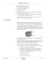
A standard wall receptacle consists of three connections: line, neutral
and ground. The figure below indicates the location of each on a 120 V
AC wall receptacle commonly used in the United States. The location and
shape of pins may be different on wall receptacles used in countries other
than the United States.
For international power outlets, refer to the internal standards agencies
of that particular country.
If other than normal polarity and ground is indicated, corrective action
must be taken before proceeding. The results of the following tests will be
meaningless unless a properly wired power outlet is used.
Use this procedure to confirm AC power from the power outlet:
1. Use a DMM to measure the voltage between the three connections.
a. Select the AC voltage scale on the DMM.
b. Measure the voltage from line to neutral, line to ground, and
neutral to ground and make sure these are correct. With a
correctly wired wall receptacle used in the United States, the
following readings should be obtained:
Line to neutral: 120 V AC
Line to ground: 120 V AC
Neutral to ground: < 3 V AC
Neutral
Line
Ground
001A
Summary of Contents for Transport Pro
Page 1: ...Transport Pro Patient Monitor Service Manual Software Version 2 2024579 018 Revision A ...
Page 9: ...Revision A Transport Pro 1 1 2012659 042 1 Introduction ...
Page 12: ...1 4 Transport Pro Revision A 2012659 042 Introduction Safety Message Definitions ...
Page 13: ...Revision A Transport Pro 2 1 2012659 042 2 Equipment Overview ...
Page 28: ...2 16 Transport Pro Revision A 2012659 042 Equipment Overview Theory of Operation ...
Page 29: ...Revision A Transport Pro 3 1 2012659 042 3 Installation ...
Page 33: ...Revision A Transport Pro 4 1 2012659 042 4 Configuration ...
Page 38: ...4 6 Transport Pro Revision A 2012659 042 Configuration Monitor Settings ...
Page 39: ...Revision A Transport Pro 5 1 2012659 042 5 Maintenance ...
Page 47: ...Revision A Transport Pro 6 1 2012659 042 6 Troubleshooting ...
Page 57: ...Revision A Transport Pro 7 1 2012659 042 7 Ordering Parts ...
Page 59: ...Revision A Transport Pro 7 3 2012659 042 Ordering Parts Exploded View Exploded View 622A ...
Page 62: ...7 6 Transport Pro Revision A 2012659 042 Ordering Parts Hardware ...
Page 63: ...Revision A Transport Pro 8 1 2012659 042 8 Disassembly ...
Page 83: ...Revision A Transport Pro 9 1 2012659 042 9 Checkout ...
Page 97: ...Revision A Transport Pro A 1 2012659 042 A Technical Specifications ...
Page 100: ...A 4 Transport Pro Revision A 2012659 042 Technical Specifications External Power Supply ...
Page 101: ...Revision A Transport Pro B 1 2012659 042 B Electromagnetic Compatibility ...
Page 109: ......

