background image

508133G01 / 31-5000715

Page 9 of 25

Issue 2140

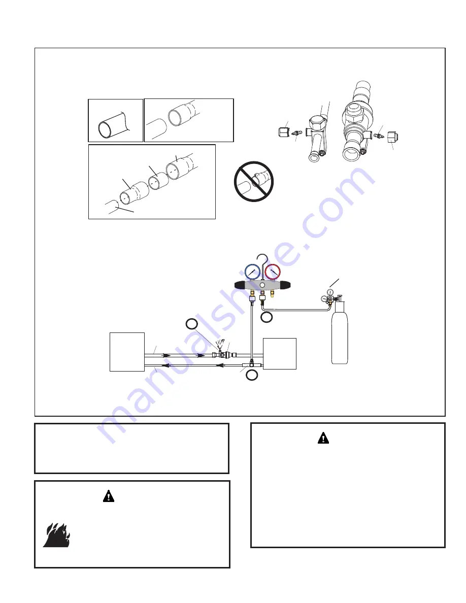
ATTACH THE MANIFOLD GAUGE SET FOR BRAZING LIQUID AND VAPOR LINE SERVICE VALVES

OUTDOOR

UNIT

LIQUID LINE

VAPOR LINE

LIQUID LINE SERVICE

VALVE

VAPOR LINE

SERVICE

VALVE

ATTACH

GAUGES


INDOOR

UNIT

VAPOR SERVICE PORT MUST BE OPEN 

TO ALLOW EXIT POINT FOR NITROGEN

 A -

Connect gauge set low pressure side to

liquid line service valve (service port).

 B -

Connect gauge set center port to bottle of

nitrogen with regulator.

 C -

Remove  core  from  valve  in  vapor  line

service port to allow nitrogen to escape.

NITROGEN

HIGH

LOW

USE REGULATOR TO FLOW

NITROGEN AT 1 TO 2 PSIG.

B

A

C

WHEN BRAZING LINE SET TO

SERVICE VALVES, POINT FLAME

AWAY FROM SERVICE VALVE.

Flow regulated nitrogen (at 1 to 2 psig) through the low-side refrigeration gauge set into the liquid line service port valve, and out of the

vapor line service port valve.

CUT AND DEBUR

CAP AND CORE REMOVAL

Cut ends of the refrigerant lines square (free from nicks or dents)

and debur the ends. The pipe must remain round. Do not crimp end

of the line.

Remove  service  cap  and  core  from

both the vapor and liquid line service

ports.

1

2

LIQUID LINE SERVICE

VALVE

SERVICE

PORT

CORE

SERVICE PORT

CAP

SERVICE

PORT

CORE

SERVICE

PORT CAP

CUT AND DEBUR

LINE SET SIZE MATCHES

SERVICE VALVE CONNECTION

DO NOT CRIMP SERVICE VALVE

CONNECTOR WHEN PIPE IS

SMALLER THAN CONNECTION

3

VAPOR LINE SERVICE

VALVE

COPPER TUBE

STUB

REFRIGERANT LINE

REDUCER

SERVICE VALVE

CONNECTION

LINE SET SIZE IS SMALLER

THAN CONNECTION

Refrigerant Piping - Brazing Procedures

Before brazing, ensure the system is fully 

recovered of all refrigerant. Application of a 

brazing torch to a pressurized system may 

result in ignition of the refrigerant and oil 

mixture. Check the high and low pressures 

before applying heat.

 WARNING

Brazing  alloys  and  flux  contain  materials  which  are 

hazardous to your health.
Avoid breathing vapors or fumes from brazing 

operations. Perform operations only in well-ventilated 

areas.
Wear gloves and protective goggles or face shield to 

protect against burns.
Wash hands with soap and water after handling brazing 

alloys and flux.

 WARNING

Use a manifold gauge set designed for use on R-410A 

refrigerant systems.

NOTE

Summary of Contents for NS18HMA

Page 1: ...ion and service performed by unqualified persons can result in property damage personal injury or death WARNING Sharp metal edges can cause injury When installing the unit use care to avoid sharp edge...

Page 2: ...ll safety codes Wear safety glasses and work gloves Use quenching cloth for brazing operations Have fire extinguisher available Read these instructions thoroughly and follow all warning or cautions at...

Page 3: ...m building not to exceed 1 4 per foot Figure 1 Slab Mounting Install on a Solid Level Mounting Pad The outdoor section is to be installed on a solid foundation This foundation should extend a minimum...

Page 4: ...warranty will be void if the drier is not installed Installation of Line Sets DO NOT fasten liquid or suction lines in direct contact with the floor or ceiling joist Use an insulated or suspension typ...

Page 5: ...listed in Table 3 Between 51 and 150 Linear Feet Crankcase heater and nonbleed port TXV factory installed No additional components required Vertical vapor riser must be sized to the vapor riser liste...

Page 6: ...iquid line size shaded row on the outdoor tonnage C Select the actual Total Linear Length of your system shown at the top of the table D The elevation listed in the table is the maximum allowed for th...

Page 7: ...ponents including line set and indoor coil must be an AHRI match with the unit in order to fulfill unit warranty requirements Fire Explosion and Personal Safety hazard Failure to follow this warning c...

Page 8: ...around the stubbed end of the check expansion valve and lightly lubricate the connector threads and expose surface of the Teflon ring with refrigerant oil 4 Attach the stubbed end of the check expans...

Page 9: ...ain round Do not crimp end of the line Remove service cap and core from both the vapor and liquid line service ports 1 2 LIQUID LINE SERVICE VALVE SERVICE PORT CORE SERVICE PORT CAP SERVICE PORT CORE...

Page 10: ...all water saturated cloths WHEN BRAZING LINE SET TO SERVICE VALVES POINT FLAME AWAY FROM SERVICE VALVE PREPARATION FOR NEXT STEP 7 WRAP SERVICE VALVES To help protect service valve seals during brazin...

Page 11: ...sig 1034 kPa Open the valve on the high side of the manifold gauge set in order to pressurize the line set and the indoor unit E After a few minutes open one of the service valve ports and verify that...

Page 12: ...r liquid refrigerant Open the manifold gauge valve 1 to 2 psig in order to release the vacuum in the line set and indoor unit G Perform the following Close manifold gauge valves Shut off HFC 410A cyli...

Page 13: ...1 is jumpered to Y2 in the outdoor unit Note that the published performance data is based upon the use of a two stage thermostat Refer to the NS18HMA field wiring diagram for a conventional 24VAC sing...

Page 14: ...hermostat Control Options Size Circuit and Install Service Disconnect Switch Refer to the unit nameplate for minimum circuit ampacity and maximum fuse or circuit breaker HACR per NEC Install power wir...

Page 15: ...100 30m 18 Temperature Rating 35 C Minimum More than 100 30m 16 Table 7 Conventional 24VAC Thermostat Wiring Route High Voltage and Ground Wires Any excess high voltage field wiring should be trimmed...

Page 16: ...RMOSTAT W L Y2 Y1 O DS C I I R DF TST Y1 O C W1 R G TC TO ACC2 ACC1 Y1 O DH C W2 W1 R G DS W2 FOR SINGLE STAGE OPERATION INSTALL A JUMPER BETWEEN Y1 TO Y2 ON THE OUTDOOR UNIT TERMINAL STRIP Figure 9 C...

Page 17: ...If the intended capacity for the application is 3 or 5 Ton skip this section The units are field convertible to 2 Ton or 4 Ton to efficiently perform for the required application If the intended capa...

Page 18: ...itiate the Charge Mode A heating blower demand must also be provided to initiate high speed blower operation on the indoor unit The compressor and outdoor fan motor will begin to ramp up and reach 100...

Page 19: ...ooling indoor blower operation In single stage thermostat applications a jumper must be installed between Y1 and Y2 on the NS18HMA outdoor control The compressor will be controlled in the variable cap...

Page 20: ...late to list the actual field charge Table 11 Refrigerant Charge Adjustment Liquid Line Set Diameter Oz Per 5 ft adjust from 15 ft line set 3 8 in 3 oz per 5 ft or 0 6 oz per 1 ft If line length is gr...

Page 21: ...testing is completed replace service port cap Tighten finger tight then an additional 1 6 turn To Open Liquid or Suction Line Service Valve 1 Remove stem cap with an adjustable wrench 2 Use service wr...

Page 22: ...in mild detergent and rinsing with cold water Allow filter to dry before reinstalling Replace filters with the arrows pointing in the direction of airflow Dirty filters are the most common cause of p...

Page 23: ...heat pump to automatically switch from heating mode to cooling mode to maintain predetermined comfort settings Many heat pump thermostats are also equipped with an emergency heat mode which locks out...

Page 24: ...Page 24 of 25 508133G01 31 5000715 Issue 2140 Figure 15 Wiring Diagram...

Page 25: ...____________ Actual Amps ______ Rated Volts _______ Actual Volts ________ Condenser Fan Full Load Amps _________ Actual Amps ______ Cooling Mode Suction Pressure ____________________ Liquid Pressure _...

Reviews: