


Page 4 of 25
508133G01 / 31-5000715
Issue 2140
Refrigerant Piping
• Use only refrigerant grade copper tubes.
• Split systems may be installed with up to 50 feet of
line set (no more than 20 feet vertical) without special
consideration (see long line set guidelines).
• Ensure that vapor and liquid tube diameters are
appropriate to capacity of unit.
• Run refrigerant tubes as directly as possible by
avoiding unnecessary turns and bends.
• When passing refrigerant tubes through the wall, seal
opening with RTV or other silicon-based caulk.
• Avoid direct tubing contact with water pipes, duct work,
floor joists, wall studs, floors, walls, and any structure.
• Do not suspend refrigerant tubing from joists and
studs with a rigid wire or strap that comes in direct
contact with tubing.
• Ensure that tubing insulation is pliable and completely
surrounds vapor tube.
It is important that no tubing be cut or seals broken until you
are ready to actually make connections to the evaporator
and to the condenser section. DO NOT remove rubber
plugs or copper caps from the tube ends until ready to
make connections at evaporator and condenser. Under no
circumstances leave the lines open to the atmosphere for
any period of time, if so unit requires additional evacuation
to remove moisture.
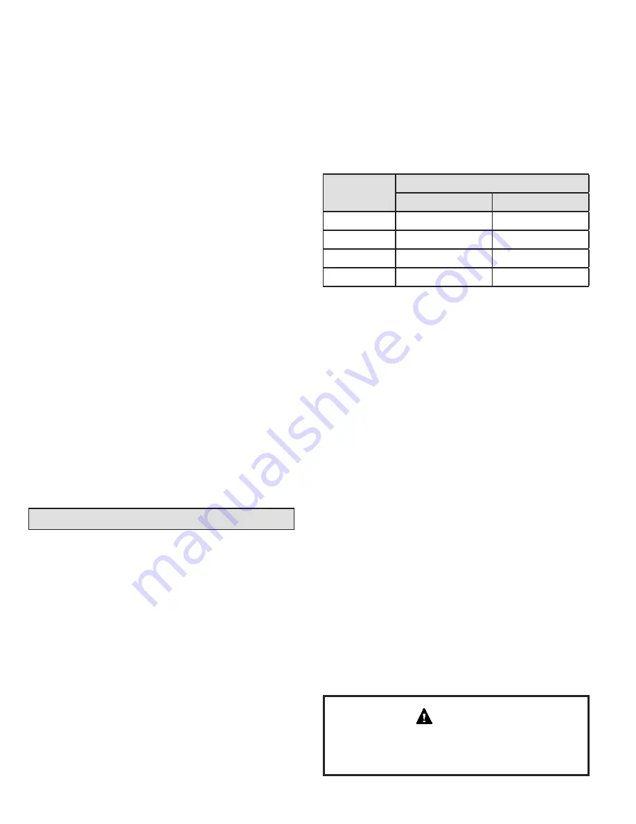
Operating
Mode
18 SEER
Liquid Line
Suction Line
2 Ton
3/8
3/4
3 Ton
3/8
3/4
4 Ton
3/8
7/8
5 Ton
3/8
1-1/8
Table 2.
Be extra careful with sharp bends. Tubing can “kink” very
easily, and if this occurs, the entire tube length will have
to be replaced. Extra care at this time will eliminate future
service problems.
It is recommended that vertical suction risers not be up-
sized. Proper oil return to the compressor should be
maintained with suction gas velocity.
Filter Drier
The filter drier is very important for proper system operation
and reliability. If the drier is shipped loose, it must be
installed by the installer in the field. Unit warranty will be
void, if the drier is not installed.
Installation of Line Sets
DO NOT
fasten liquid or suction lines in direct contact with
the floor or ceiling joist. Use an insulated or suspension
type of hanger. Keep both lines separate, and always
insulate the suction line. Liquid line runs (30 feet or more)
in an attic will require insulation. Route refrigeration line
sets to minimize length.
DO NOT
let refrigerant lines come in direct contact with
foundation. When running refrigerant lines through the
foundation or wall, openings should allow for a sound
and vibration absorbing material to be placed or installed
between tubing and foundation. Any gap between
foundation or wall and refrigerant lines should be filled with
a vibration damping material.
If ANY refrigerant tubing is required to be buried by state
or local codes, provide a 6 inch vertical rise at service
valve.
CAUTION
DO LOCATE THE UNIT:
• With proper clearances on sides and top of unit
• On a solid, level foundation or pad (unit must be level
to within ± 1/4 in./ft. per compressor manufacturer
specifications)
• To minimize refrigerant line lengths
DO NOT LOCATE THE UNIT:
• On brick, concrete blocks or unstable surfaces
• Near clothes dryer exhaust vents
• Near sleeping area or near windows
• Under eaves where water, snow or ice can fall directly
on the unit
• With clearance less than 2 ft. from a second unit
• With clearance less than 4 ft. on top of unit
Operating Ambient
The minimum outdoor operating ambient in cooling mode
is 55°F, and the maximum outdoor operating ambient in
cooling mode is 125°F. The maximum outdoor operating
ambient in heating mode is 66°F.
Rooftop Installations
Install unit at a minimum of 6” above surface of the roof
to avoid ice buildup around the unit. Locate the unit
above a load bearing wall or area of the roof that can
adequately support the unit. Consult local codes for rooftop
applications.
If unit cannot be mounted away from prevailing winds, a
wind barrier should be constructed. Due to variation in
installation applications, size and locate barrier according
to the best judgment of the installer.


