MAINTENANCE: Checkout Procedure
3-8
APEX Telemetry Transmitter
Revision D
401566-166
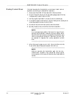
Battery Current Draw
This test measures the transmitter current draw in both normal
operation and during an all-leads-fail condition.
1.
Disconnect the APEX RF test cable from the transmitter.
2.
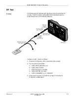
At point B (see the figure on the preceding page) adjust the low-
voltage power supply output to 3.0V.
3.
Set the digital multimeter to measure current (milliamps).
4.
Connect the digital multimeter in series at test point A (see figure on
preceding page) to measure current flow.
5.
Reconnect the APEX RF test cable to the transmitter.
6.
Quickly measure the current flow into the transmitter.
NOTE
In an all-leads-fail condition that lasts for longer than 6
seconds the transmitter reduces its power output. When
the APEX RF test cable is connected the transmitter goes
into an all-leads-fail condition. Therefore you have only
six seconds to measure the normal operation current
flow.
7.
When the power supply level is 3.0V, the current flow into the
transmitter should measure between 24 to 30 mA.
NOTE
After six seconds, the transmitter goes into the ALL-
LEADS-FAIL condition. The reduced RF output results
in a reduction in the current flow into the transmitter of
4-6 mA.

