


FP1500 Installation, Configuration and Commissioning Manual
44
•
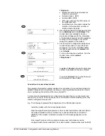
The general parameters are adjusted
Choose language (See section 4.1)
Standby and General Fault Message (See section 4.1.1)
Adjust Time and Date (See section 4.1.2)
•
Configure loops (See section 4.1.3)
Auto-search (See section 4.1.3)
From the external PC, configuration software:
(If you do not have a computer, it can also be configured through the control unit panel)
•
Editing of Zone (See section 4.1.4)
•
Editing of Texts
(See section 4.1.5)
•
Editing of logic lines
(See section 4.1.6)
•
Allocation of logic lines to the loop elements
(See section 4.1.7)
•
Load the configuration from the PC to the control unit
(See section 4.1.8)
5.3 Operational tests
Once the connections have been checked and the system is fully configured, it is
important to perform functioning tests on the connected elements.
The installer must trigger all the sensors and check that the system carries out the
appropriate logic lines, in accord with the implanted configuration.
5.4 Troubleshooting guide
5.4.1 Earth
faults
The system detects if a current leakage to earth occurs. The FP1500 indicates this
through the “Earth Fault” LED. Even though this does not normally adversely affect the
operation of the system, this fault needs to be resolved as soon as possible.
A problem involving leakage to earth adversely affects the ability of the system to handle
external interference. This may lead to communication errors with the devices.
Disconnect the power supply when working with the system.
5.4.2 Communication
errors
Caused by interference in the communication cables or by an open or short circuit fault in
the loop.
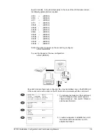
Leakage of the communication cables:
If the voltage is correct in the control unit and the sensors - approx. 32 V when checked
with a tester (see section 7 Technical specifications for details) - indicate that interference
or leakage has occurred in the cables:
•
To find the point of interference, disconnect one of the ends of the installation and
make a connection on the loop base, between S+ and R+ and between S- and R- to
ensure the functioning of the control unit and that there is no Open circuit fault.