


FP1500 Installation, Configuration and Commissioning Manual
19
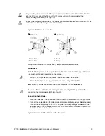
KAL
785/701
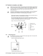
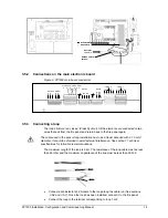
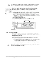
3.5.7 Connecting relays
Relays outputs can be connected to the corresponding sockets on the main board (the
ones furthest to the left). It is important to ensure that the terminals are tightly fixed.
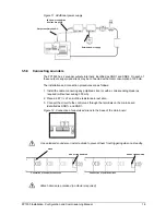
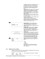
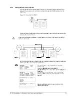
Figure 13. Connection of relays on the main board
The relay output has three terminals:
C
: common
NA
: normally open
NC
: normally closed
The EN54 standard requires a normally activated (fail-to-safe) fault relay. One of these
relays may be used for this function (See section 4.1.7 for the Configuration of relay output).
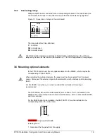
3.6 Mounting optional elements
In the FP1500 control unit, the only optional element is the RS485, which requires the
corresponding IC (KAL785/701).
When installing the optional elements, the panel must be disconnected from the power
supply. Disconnect the external magneto-thermal switch and the batteries before inserting
the IC.
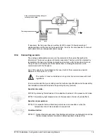
For the RS485 connections, you must use cable that is stranded. Screening is
recommended.
The FP1500 has two serial communications ports on board. Port 1 is allocated to the
RS232 and is incorporated in the main board at the factory. Port 2 is allocated to RS485
and this is optional.
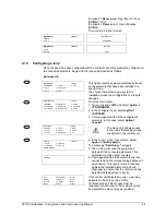
For the RS485 option to be available, the KAL785/701 IC must be installed in the
corresponding slot on the main board.
KAL785/701 IC optional for RS485
Installing the IC:
1. Disconnect the fire panel from the supply
NA
NC
C
RELAY2
RELAY1
NA
NC
C