


FP1500 Installation, Configuration and Commissioning Manual
8
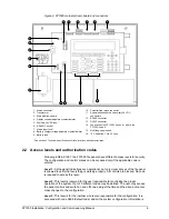
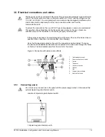
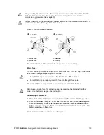
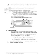
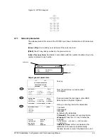
Figure 4. FP1500 main electronic board and connectors
1. Mains connector *
2. Transformer
3. Main electronic board
4. Display contrast adjustment potentiometer
5. Auxiliary 24 VDC fuse *
6. RS485 IC socket
7. Mains Input fuse *
8. Battery charger voltage adjustment potentiometer
9. Battery fuse *
10. Potential-free relays connector
11. Supervised sounders and auxiliary 24 VDC
connectors
12. RS485 connector
13. RS232 connector
14. Loop connector: FP1500/1 has only 1 where the
FP1500/2 has 2
15. Multi-language inserts
16. 12 V batteries: 7 A/h x 2 units
* See section 7 Technical specifications for fuse locations and characteristics.
2.2 Access levels and authorization codes
Following EN54-2:1997, the FP1500 fire panels have different access levels for security.
The configuration and control menus can be accessed only if the applicable code is
entered.
Level 1:
All the panel indications are operational, but only visual access of the fire panel
is allowed to verify that everything is working properly. All controls are blocked. No code
is required to access this level.
Level 2:
This level is reserved for the user responsible for controlling the proper
operation of the system. Up to 10 different codes may be defined. The user may access
the panel controls and switch on and off zones, adjust the time and the date, but cannot
make changes to the configuration.
Level 3:
This level is for the installer who is also responsible for the configuration. It is
accessed with code 9898 (default code) and all the system configuration information is
2
1
3
4
5
7
8
9
10
11
12
13
14
15
16
6