


FP1500 Installation, Configuration and Commissioning Manual
13
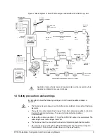
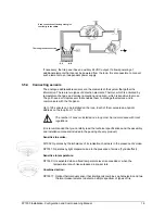
For your safety, the order in which the power is reconnected must be: Mains first, then the
batteries. Do not connect the fire panel to the mains until you have completed the
commissioning procedure (See chapter 5).
Connect the mains on the outside of the cabinet and with an adequate earth connection. The
earth cable should be the longer of the three cables.
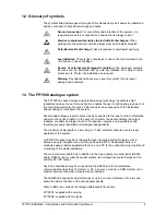
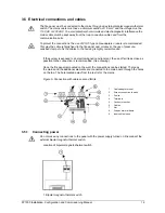
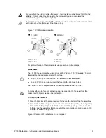
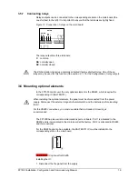
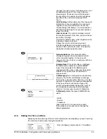
Figure 7. FP1500 mains connection
X
110 VAC
Y
230 VAC
1. Mains fuse
3. Neutral
2. Mains fuse
4. Clamp
For optimum fixation of the mains cable, use pressure-sensitive clamps
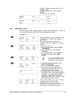
Mains fuses
The FP1500 fire panel can be supplied from a 230 VAC or a 110 VAC supply. The mains
fuse must be changed depending on the voltage.
•
For a 110 VAC power source, insert the fuse into the left fuse holder.
•
For a 230 VAC power supply, insert the fuse into the right fuse holder.
See section 7 Technical specifications for fuse locations and characteristics.
Do not use the mains fuse for connecting and disconnecting the fire panel from the
mains. Use the bipolar magneto-thermal switch.
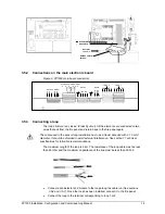
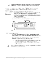
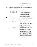
Connecting the batteries
1. Place the batteries in the space reserved for them at the bottom of the fire panel box.
2. Connect the cables taking the colour codes into account (red positive, black negative).
Connect the battery bridge cable that is supplied with the package, between the two
batteries and the two cables that come out of the main electronic board to each of the
batteries as shown in the picture.
Figure 8. Placement of the batteries in the fire panel