


FP1500 Installation, Configuration and Commissioning Manual
12
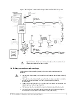
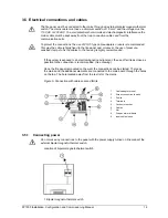
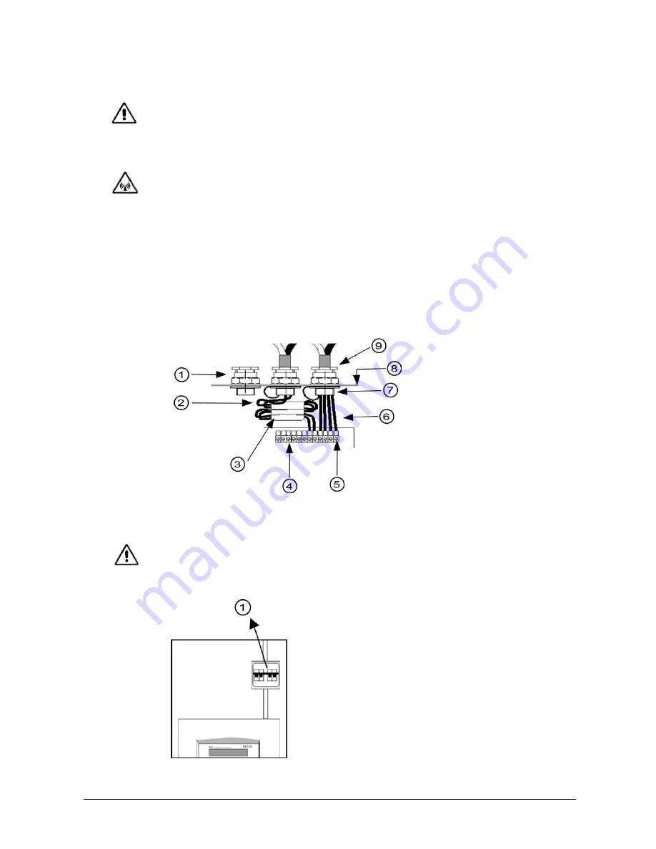
3.5 Electrical connections and cables
The fire panel must be connected to the mains through an external bipolar magneto-thermal
switch. The mains cable must have a minimum section of 1.5 mm² and the voltage must be
110 VAC or 230 VAC. To avoid potential short-circuits and electromagnetic interference the
mains cable must be kept away from the loop connection cables and from the
communication ports.
To protect the connections, the use of PG11-type cable adapters or seals is recommended.
This way the cable is firmly fixed to the fire panel and, moreover, the use of pressure-
sensitive clamps to fix the cables to the housing is highly recommended.
If the system is exposed to an electromagnetic environment, the use of ferrite as close as
possible to the connection is recommended.
(See drawing)
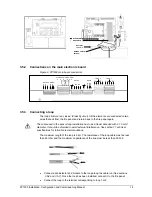
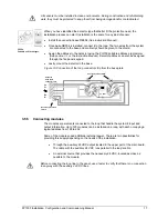
Once the fire panel is mounted on the wall, the connections can be started. The loops,
the mains and the additional elements are connected to the main board through the holes
on the top. The hole located away from the rest is for the mains.
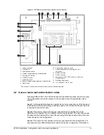
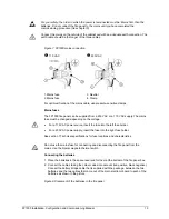
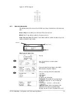
Figure 6. Connection with cable seal and ferrite
1.
Cable adapter or seal
2.
Screen connection to earth
3. Ferrite
4. Terminals
5. Connector
socket
6. Cables
7. Nut
8.
Fire panel metal frame
9.
Input cable sleeve
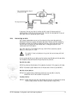
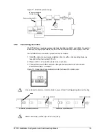
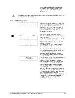
3.5.1 Connecting
power
Do not make any connections to the panel with the power supply turned on. Disconnect the
external bipolar magneto-thermal switch.
Location of bipolar magneto-thermal switch
1. Bipolar magneto-thermal switch