Modifications reserved
Page 13/90
GE_UPS_USM_TLE_SUL_40K_M15_1US_V010.docx
User Manual
TLE Scalable Series 40 - 150 UL S1
4.2
OPERATION MODES
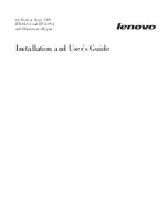
4.2.1
Normal VFI Operation Mode (Voltage Frequency Independent)
Under normal conditions the
Load
is
permanently powered by the
Inverter
with
constant amplitude and frequency.
The
Rectifier
, powered by the
Utility
, supplies
the
Inverter
and the
battery-charger
keeps the
battery
fully charged.
The
Inverter
converts the DC voltage in a new
AC sine wave voltage with constant amplitude
and frequency independently from the input
Utility Power
.
Fig. 4.2.1-1 Block diagram normal VFI Operation Mode
4.2.2
SEM Operation Mode (Super Eco Mode)
When the
SEM Operation Mode
is selected,
and the
Utility Power
is available, the
Load
is
normally powered through the
Automatic
Bypass
.
When the
Utility Voltage
is detected out of the
prescribed tolerances, the
Load
is
automatically transferred to the
Inverter
.
When the
Utility
recovers, the
Load
returns to
the
Automatic Bypass
after a variable time
defined by the control unit.
Fig. 4.2.2-1 Block diagram SEM Operation Mode
The
SEM Operation Mode
can be configured directly by the user for higher efficiency, considering the
Utility
reliability and criticality of the
Load
.
The selection between the two operation modes “
VFI
mode and
SEM Operation Mode
”, or switching
between operation modes at required time, can be done through the UPS
control panel
(see
Section 6.4
/ SEM
).
In case of Parallel System
“SEM – Super Eco Mode” Operation Mode
cannot be enabled for RPA Parallel System.
Attention:
A single unit equipped with a RPA - Parallel board, must be considered as parallel, thus
disabling SEM Operation Mode.