background image

Passwords

18

4

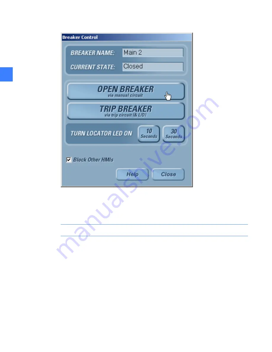
Figure 4-6

Breaker Control screen

The CPU reserves a communication port for the HMI with the Local HMI flag set. The CPUs 
can support up to 8 simultaneous communication ports for Modbus clients. Once the limit is 
exceeded, clients will be blocked until a port is free. The Local HMI flag has special ports 
reserved for its use to prevent other clients from locking it out.

NOTE:

All In-Gear and Near-Gear Touchscreen HMIs should have the “Local HMI” set.

To set an HMI as a local HMI
1.

On the 

Main Menu

, click the 

Maintenance

 button. The button will only be displayed if access 

is allowed with the current login permissions.

2.

Click the 

Modbus Security

 tab. 

3.

Select the 

Local HMI

 check box as shown in Figure 4-5.

4.

Click the 

OK

 button to save changes (or click 

Cancel

 to cancel changes).

Summary of Contents for Entellisys DEH-230

Page 1: ...GE Entellisys Low Voltage Switchgear System Administrator Manual ...

Page 2: ...fforts have been made to ensure accuracy the information contained herein does not cover all details or variations in hardware and software nor does it provide for every possible contingency in connection with installation operation and maintenance Features may be described in here that are not present in all hardware and software systems GE Consumer Industrial assumes no obligation of notice to h...

Page 3: ...the Entellisys HMI on the System Health screen by clicking the Job Info button Post Sales Service GE Switchgear 510 Agency Road West Burlington IA 52655 Phone toll free 1 888 437 3765 Additional information www entellisys com support For Option Upgrades and CPU Replacement needs only e mail us at entellisys lvs pss ge com ...

Page 4: ......

Page 5: ...te communication 22 6 1 1 HMI IP address 22 6 1 2 CPU IP address 22 6 2 Network security VPN device 24 7 Installing and configuring remote HMI software 8 Settings files and offline system configuration 8 1 Offline mode 29 8 2 Viewing and comparing settings files 31 8 3 Writing settings to a live system 33 8 4 Resetting the offline settings files to the current settings 34 9 Sharing files across HM...

Page 6: ... functions 13 1 Viewing and updating circuit breaker names 55 13 2 Viewing and updating circuit breaker accessories 56 13 3 Installing CPU firmware 58 13 4 Viewing zone configuration 59 14 Administrator access to the operating system ...

Page 7: ...d passwords The System Administrator determines who needs what permissions and assigns login names and passwords Modbus Settings and Control Access Remote Access to the Switchgear over a company network Security Reminders Limit the access level handed out to only the required permissions Stress the importance of keeping passwords secret If you believe passwords have been compromised change them im...

Page 8: ...System administrator roles and responsibilities 8 1 ...

Page 9: ...ntellisys Remote HMI User Interactive version software See Installing and configuring remote HMI software on page 25 for instructions Step 2 Install the System Archive provided by GE See Restoring an archive on page 38 for instructions Step 3 Change to Offline Mode See Offline mode on page 29 for instructions and for offline mode capabilities Step 4 Set User Settings See DEH 231 Entellisys Low Vol...

Page 10: ...Pre programming settings prior to switchgear arrival 10 2 2 ...

Page 11: ...witchgear Step 1 Reset Passwords See Passwords on page 13 Step 2 Set User Settings See DEH 231 Entellisys Low Voltage Switchgear System User Manual Step 3 Set Local HMI flags See Local HMI on page 17 Step 4 Set System Time Synchronization See Time synchronization on page 19 Step 5 Configure System for Remote Communications See Configuring the switchgear for remote communications on page 21 ...

Page 12: ...Commissioning the switchgear 12 3 ...

Page 13: ...e changing of settings and or access to control functions must be restricted to accounts for qualified personnel only As a reminder users with such privileges will be presented with the following screen upon initial login Figure 4 1 Initial login Caution screen 4 1 1 Setting HMI login permissions and passwords A Group defines the permission categories for a type or group of users By default Admini...

Page 14: ...dministrator Group Operator User not defined Group Guest User Guest Figure 4 3 User Administration screen in the HMI To set permissions for a user Group 1 On the Main Menu click the User Administration button Only Administrators can access User Administration For all others the button will not appear on the Main Menu 2 Click the desired user group to edit or click the Add Group button to define a ...

Page 15: ...ange 1 On the Main Menu click the Change Users icon in upper right hand corner Figure 4 4 Change Users icon 2 Enter the user name in the Login field 3 Enter the new password in the password field 4 Click Go If successful the Main Menu will display 4 1 2 Resetting forgotten HMI passwords Administrators have access permission to change passwords for all users in all groups NOTE It is very important ...

Page 16: ...system through Modbus communications including the Entellisys HMI SCADA or Building Automation etc NOTE The system ships with default CPU Modbus Settings and Command passwords The System Administrator should change these passwords for added security The HMI can be configured to transparently send the passwords whenever needed or it can be configured to require all users to re enter the password wh...

Page 17: ...d for the CPU that is currently the default each time a command is sent NOTE For added security it is recommended the Auto Send option be disabled This will require an additional password to be entered each time a command is performed 4 2 2 Local HMI An Entellisys system may have multiple HMI stations running There are some functions that should be performed by one HMI only The Local HMI flag is p...

Page 18: ... flag has special ports reserved for its use to prevent other clients from locking it out NOTE All In Gear and Near Gear Touchscreen HMIs should have the Local HMI set To set an HMI as a local HMI 1 On the Main Menu click the Maintenance button The button will only be displayed if access is allowed with the current login permissions 2 Click the Modbus Security tab 3 Select the Local HMI check box ...

Page 19: ...istent Time synchronization configuration is done by GE during the system start up NOTE The System Administrator should periodically check the date and time set on all local HMIs to ensure the event time stamps are accurate It is especially important on the HMI configured to time synch the CPUs 5 0 1 Setting time in the HMI To set time log into the HMI Operating System with Administrator access se...

Page 20: ...Time synchronization 20 5 ...

Page 21: ...he network segment on which each device resides Gateway IP depends on the company network and needs to be acquired from the Network Administrator Step 2 Reset the CPU IP Addresses See Setting IP addresses for remote communication on page 22 Step 3 Reset the local HMI IP Addresses See Setting IP addresses for remote communication on page 22 Step 4 Verify communication between the local HMIs and CPU...

Page 22: ...open the Network Connections dialog box 3 Double click the Local Area Connection 1 4 In the TCP IP Properties tab set the new Local HMI IP address Set the subnet mask to a value compatible with the segment on which it resides By default the subnet mask is set to 255 255 255 0 The default touchscreen HMI IP address is 192 168 1 1 as delivered The default IP address for each additional touchscreen H...

Page 23: ...s to establish communication with the CPU 7 In unable to connect a dialog box will display Click the Retry button to test communication again or click Cancel to exit 8 The Communication status with the new IP address will display below the IP address edit dialog box For example CPU A System Running OK Communication with new IP address is success CPU B System Unavailable Failed to communicate with ...

Page 24: ...Gear and Near Gear HMIs The implications for network security depend on the accessibility of the network the Near Gear HMI uses to reach the main switchgear instrumentation compartment In Gear Near Gear Remote HMIs and SCADA system access The implications for network security depend on the accessibility of the network the Near Gear HMI uses to reach the main switchgear assembly GE provides a mecha...

Page 25: ...y the target computer meets the requirements before proceeding Step 2 Install and launch the HMI program Insert the Entellisys Remote HMI CD and run the install program Follow the onscreen installation wizard Click Finish to complete the installation To start the Entellisys Remote HMI application point to Start select Programs and then double click Entellisys LVS HMI Step 3 Activate the software w...

Page 26: ...nformation ready Entellisys System Identifier Summary Sub HMI Type User Interactive or Viewer on the blue title bar in Figure 7 1 SITE CODE from the activation window in Figure 7 1 MID CODE from the activation window in Figure 7 1 GE will verify that unused licenses of the desired version are available and will provide an Activation code for the software Type in the Activation code and click Conti...

Page 27: ...d Files During the Remote HMI installation generic files are loaded The custom system files corresponding to a particular system must be obtained for proper screens and configuration Otherwise blank oneline elevation and control panel screens will be shown the advanced protection configuration and zone settings will not be shown and other maintenance configuration will not be set Entellisys provid...

Page 28: ...Installing and configuring remote HMI software 28 7 ...

Page 29: ...s between CPUs does occur an event will be generated A mismatch should be correctly immediately 8 1 Offline mode The HMI has a special offline mode Offline mode disconnects the HMI from a live system and allows users to modify and save settings Later once reconnected to a live system these saved settings can be written to the system The following operations are permitted in offline mode User Setti...

Page 30: ...ab 3 Select the Work Offline check box to change to offline mode This can be found in the lower right hand corner in Figure X chapter 2 1 dk no section 2 1 HMI will go into offline mode and disconnect from the live system HMI will connect to the live system An icon on the bottom right screen displays to indicate that the application is in offline mode Figure 8 2 Offline mode icon The first time of...

Page 31: ...play the settings associated with a particular settings file To view any settings file click the filename in the right side pane click Load and the settings will display As mentioned in Chapter 2 it is important to keep the settings in both CPUs consistent The HMI can compare two settings files and highlight differences To compare two settings files 1 On the Main Menu click the Maintenance button ...

Page 32: ...Settings files and offline system configuration 32 8 Figure 8 3 Settings file compare screen ...

Page 33: ...ill only display if access is allowed with the current login permissions 2 On the Maintenance screen click the Settings File tab 3 Verify the HMI is connected to the system clear the Work Off Line check box 4 Select the offline settings to download Once selected the settings values will display on the screen 5 Click Write To The screen in Figure 8 4 will display Figure 8 4 Write Settings screen ...

Page 34: ...communicating 7 Click the Write button to send the settings to the selected CPU 8 Repeat steps 5 to 7 for the second CPU 8 4 Resetting the offline settings files to the current settings It may be desired to reset the offline settings files to the current settings To copy current settings to the offline settings files 1 On the Maintenance screen click the Settings File tab and then select the setti...

Page 35: ...screens Alarm configuration Circuit breakers are added to the system or circuit breaker maintenance is updated Advanced protection zones tiers or topologies change To publish shared files for other HMIs to retrieve 1 On the Main Menu click User Settings 2 Click HMI Preferences 3 In the HMI Preferences dialog box click General 4 In the HMI Shared File dialog box click the Update CPUs button Only th...

Page 36: ... click User Settings 2 Click HMI Preferences 3 In the HMI Preferences dialog box click General 4 Click Update HMI 5 Click Yes in the confirmation dialog box to proceed by loading the shared files Or click No to cancel the operation 6 Once the file transfer is complete a list of transferred file names is displayed Click OK to complete the process ...

Page 37: ... An archive is created and shipped to the System Administrator when the switchgear ships from the factory The archive may be installed in a Remote HMI application allowing users to pre program protection settings prior to the switchgear arrival Archives are recommended at the following events At switchgear startup once the system settings have been programmed and tested Periodically throughout the...

Page 38: ... proceed 7 The Archive is now restored Click the Close button to exit The system will automatically eject the USB device 8 Next a dialog box will prompt you to restart the system The system must be restarted for the new settings to take effect The following files are restored in the process Setting Files Multipoint Configuration and Breaker Settings One Line Elevation Files and Control Panel scree...

Page 39: ...7 Select the USB drive Once a valid drive is selected the Backup button is automatically enabled 8 Select the folder where you want the archive to be created 9 Click the Backup button A subfolder with the current date and time stamp is automatically created On successful completion of the backup a message will display Backup has been taken in the following directory subfolder name Please Close the...

Page 40: ...System archives 40 10 ...

Page 41: ...e through software upgrades 11 1 Viewing installed options 1 On the Main Menu click the Maintenance button The button will only be displayed if access is allowed with the current login permissions 2 Click the Options tab to view current installed software options as shown in Figure 11 1 Figure 11 1 Installed Options screen ...

Page 42: ...essed from the front of the switchgear behind the small door in the bottom right corner of the HMI 2 On the Main Menu click the Maintenance button The button will only be displayed if access is allowed with the current login permissions 3 Click the Upgrade Options tab as shown in Figure 11 1 Figure 11 1 Upgrade Options screen 4 In the Request Option Upgrade group click the Save Request To USB butt...

Page 43: ...his port is accessed from the front of the switchgear behind the small door in the bottom right corner of the HMI 2 On the Main Menu click the Maintenance button The button will only be displayed if access is allowed with the current login permissions 3 Click the Open Options String File button in the Upgrade Option String group 4 In the Browse CPU Option File dialog box select the Option string f...

Page 44: ...Feature options 44 11 ...

Page 45: ...ed in the DEH 234 Entellisys Low Voltage Switchgear Device Replacement Guide Chapter 1 Replacing a CPU chassis Please read these instructions thoroughly prior to beginning the replacement 12 1 Part I Preparation for replacement of a CPU On the Maintenance screen click the Replace CPU tab Click Perform Preparation This will bring up the Step 1 Select CPU dialog box Select which CPU is to be replace...

Page 46: ...acement CPU 46 12 After clicking Next the following instructions will display Figure 12 2 Read Option String dialog box Save the old Option String to the memory stick and click Next Figure 12 3 Browse CPU Option String File dialog box ...

Page 47: ...PU 47 12 The rest of the instructions for preparing for the replacement are shown on the screens for steps 3 and 4 of the preparation dialog box Figure 12 4 Step 3 CPU Serial Number dialog box Figure 12 5 Step 4 Preparation Finished dialog box ...

Page 48: ... wizard This wizard assists in replacing the CPU and modifying the IP Address Configuration Firmware Option String Settings and CPU Commission options The Step 1 Select CPU dialog box displays again to confirm which CPU is to be replaced Figure 12 6 Step 1 Select CPU dialog box After clicking Next The following dialog box reminder will display Figure 12 7 Step 2 Option String dialog box ...

Page 49: ...option string the Step 3 Set Default IP dialog box will display as shown below This will change the configured address within the HMI to the default address of a new CPU in preparation for communicating with it in Step 4 NOTE If the IP Address of the CPU has already been set to the default IP address select Skip This Task and click Next Otherwise click Next The current IP configuration will be sto...

Page 50: ...splay confirming the status of changes as they are being made NOTE After performing this step the CPU may be powered down and physically swapped out Please refer to DEH 234 Entellisys Low Voltage Switchgear Device Replacement Guide Chapter 1 Replacing a CPU chassis for this procedure prior to proceeding to the next section ...

Page 51: ...d in the Step 4 dialog box select the Skip This Task check box prior to clicking Next Otherwise leave the check box cleared and just click Next Figure 12 10 Step 4 Set Original IP dialog box A confirmation dialog box will display asking for confirmation that the old CPU has been replaced and the new CPU is installed and has been powered on for at least 2 minutes Figure 12 11 Entellisys LVS HMI dia...

Page 52: ...me reason there is a mismatch in the version number exit out of the procedure by clicking Cancel and restart the procedure from the beginning of this section Figure 12 12 Step 5 CPU Firmware dialog box Click Next to proceed to Step 6 Click Next to update the option string This task may be skipped by selecting the check box if the new CPU is known to already have the correct option string Figure 12...

Page 53: ...update the settings to the new unit The option to skip the task is available if this has already been done Figure 12 14 Step 7 Copy Setting dialog box Finally the dialog box for Step 8 will display Commissioning the new CPU will activate all of the relaying and protection algorithms in the unit Click the Finish button to complete the process Figure 12 15 Step 8 Set CPU Commission dialog box ...

Page 54: ...Preparing and configuring a replacement CPU 54 12 ...

Page 55: ... with the current login permissions 2 Click the Breaker Names tab A table will display as shown as in Figure 13 1 Figure 13 1 Breaker Names screen Breaker ID Unique identifier for the circuit breaker This is set by GE and cannot be changed Breaker Name Unique name given to a circuit breaker 16 alphanumeric characters This may be set in the factory if information is provided from the customer Other...

Page 56: ...alled accessories Breaker Racking Position status is available only if the position switch accessory is installed Electrically Locked Out status is available only if either the Bell Alarm or Network Interlock accessory is present Closing Spring Status is available only if the Electric Operated accessory is present Additionally the Breaker Control relies on the electric operated circuit breaker acc...

Page 57: ...aker to be opened closed and charged remotely The check box should be selected if this accessory is present LockOut Circuit breaker contains either a bell alarm lockout accessory to prevent reclosing after tripping or a network interlock accessory to prevent closing during automatic throw over The check box should be selected if this accessory is present Position Switch Circuit breaker contains an...

Page 58: ...loaded Figure 13 3 CPU Firmware Download screen To download new firmware to the CPUs 1 On the Main Menu click the Maintenance button The button will only be displayed if access is allowed with the current login permissions 2 Click the CPU Firmware tab 3 Click the Browse button to select a CPU firmware file 4 Locate the CPU firmware file and click the Open button 5 If the selected file is valid the...

Page 59: ...ion screen gives an overview of the global zone configuration and also for each protection function Multi Source Ground Fault Bus Differential and Zone Selective Interlock See DEH 231 Entellisys Low Voltage Switchgear System User Manual Chapter 6 Zones buses and topologies for details ...

Page 60: ...Other maintenance functions 60 13 ...

Page 61: ...computer It is strongly recommended that the System Administrator limit knowledge of this ability to prevent unauthorized access Steps to get Administrator access to the operating system of an HMI Touchscreen Computer 1 Press Ctrl Alt Delete A Windows Security dialog box will display 2 Press the Logoff button 3 Constantly press the Shift key until the login dialog box Login On Windows as displays ...

Page 62: ......

Reviews: