


g
GE
OPM_SGS_USM_10K_40K_0US_V010.doc
15/88
Operating
Manual
SG Series
10, 20, 30 & 40 kVA
3.3.2 Features of RPA parallel system
The
SG Series
parallel system is designed to provide a complete
Redundant Parallel
Architecture
, and is free from common equipment.
Not only the
Inverters
are redundant, but also the
Bypass
functions are designed with
redundant modular concept.
When one UPS needs maintenance or service, the
Load
is powered by the other units
supplying the
Load
bus.
The redundant communication bus to which all units are connected keeps each unit informed
about the status of all the other units.
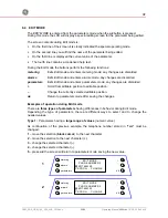
The
control panel
located on each unit allows controlling and monitoring the status of this
unit.
3.3.3 System
control
A
high-speed redundant, serial communication
bus guarantees the exchange of data and
thus the communication between the CPU's of each unit.
Each module controls it's own function and operational status and communicates with all other
modules, in order to act or react if necessary, adapting it to the new conditions.
3.3.4 Synchronization
All units are identical, but one unit is arbitrarily selected as the reference and all the other units
synchronize to this unit, which in turn, synchronizes to the
Utility Bypass
voltage, as long as
the later is within tolerances.
In case of reference failure, another unit in the parallel system is automatically chosen to take
over the reference role.
The
Bypass Input
for all the units of the parallel system must be supplied from the same AC
source (no phase shift allowed between them).
3.3.5 Load sharing
On each unit of the parallel system,
Inverter Output Voltage
and
Current
are measured and
applied to a
Load
sharing bus.
An eventual difference between the units is therefore automatically equalized.
It is strongly recommended that no transformers, automatic circuit
breakers or fuses should be inserted between the unit’s output and the
Load
common bus bars.
However, it is recommended that a disconnect or isolation switch be
inserted.


