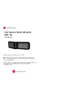
7.2.2 DC Link Fuses
There are two DC link fuses for each inverter located on top of the inverter.
1.
Remove covers from inverter cabinet to gain access.
2.
Remove bus bars securing top of fuses by removing attaching bolts (8mm).
3.
Remove bolts securing bottom of fuses (8mm).
2
3
1
4
5
1
Top (-)DC link fuse bus bar
4
(+)DC link fuse
2
(-)DC link fuse
5
Bottom (+)DC link fuse bus bar
3
Top (+)DC link fuse bus bar
High Power Service Manual for Unit Sizes 6x
100
7
Summary of Contents for AF-650 GP Series
Page 31: ...High Power Service Manual for Unit Sizes 6x 30 3...
Page 41: ...Illustration 3 7 Inverter section High Power Service Manual for Unit Sizes 6x 40 3...
Page 43: ...Illustration 3 8 Brake option High Power Service Manual for Unit Sizes 6x 42 3...
Page 97: ...High Power Service Manual for Unit Sizes 6x 96 7...
Page 111: ...High Power Service Manual for Unit Sizes 6x 110 8...
Page 121: ...High Power Service Manual for Unit Sizes 6x 120 9...
Page 134: ...11 Block Diagrams High Power Service Manual for Unit Sizes 6x 133 11...