2
B e f o re using your oven, read this
book care f u l l y.
It is intended to help you operate and maintain your new
stove properly. Keep it handy for answers to your
questions.
If you received a damaged stove…
Immediately contact the dealer (or builder) that sold you
the stove.
Save time and money.
B e f o re you request serv i c e …
Check the Problem Solver in the back of this guide. It
lists causes of minor operating problems that you can
correct yourself.
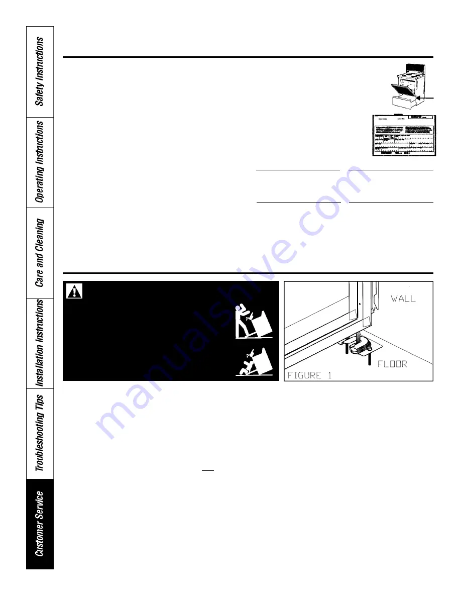
Write down the model
and serial numbers.
You’ll find them on a label behind
the storage drawer.
These numbers are also on the
Ownership Registration Card that
came with your stove. Before
sending in this card, please write
these numbers here.
Installation instructions are provided for wood and concrete floors. Any other type of construction may require special
installation techniques to provide adequate fastening of the ANTI-TIP bracket to the floor.
Note: The installation of the ANTI-TIP bracket must meet all local codes for securing appliance.
The use of this bracket does not preclude tipping of the range when not properly installed.
Be sure that screws do not penetrate electrical wiring or plumbing.
1.
Push range into exact position where you intend to install it.
2.
Remove storage drawer by pulling it all the way out, then lifting the front of the drawer to allow the wheels to come
out of their tracks. (See Use & Care Guide.)
3.
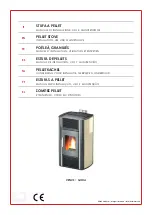
Slide the anti-tip bracket over one of the rear leveling feet as shown (Fig. 1).
4.
Mark its location on the floor with a pencil.
5.
Pull the range out of the way and reposition the bracket using your pencil marks from step 4.
6.
Drill 2 holes into the floor (1/8” for “wood floor” or recommended size hole for hardware for “concrete floor”).
Hardware 1/4” x 1-1/2” lag bolt & 1/2” O.D. sleeve anchor not provided.
7.
Screw the bracket to the floor using screws provided for “wood floor” or lag bolt & O.D. sleeve anchor (not
provided) for “concrete floor”.
8.
Slide the range into position, ensuring that the leveling foot fully engages in the slot in the anti-tip bracket.
9.
Test the installation by grasping the top edges of the rear surface and carefully attempt to tilt the range forward.
HELP US HELP YOU
I N S TA L L ATION OF ANTI-TIP BRACKET
Model Number
Serial Number
Retailer’s Name
Date of Purchase
Use these numbers in any correspondence or service
calls concerning your stove.
• RANGE MUST BE SECURED BY THE
ANTI-TIP BRACKET SUPPLIED IN THE
BAG.
• UNLESS PROPERLY INSTALLED, THE
RANGE COULD BE TIPPED BY
STEPPING OR SITTING ON THE DOOR.
INJURY MIGHT RESULT FROM SPILLED
HOT LIQUIDS OR FROM THE RANGE
ITSELF.
WARNING: SAFETY INSTRUCTIONS
Summary of Contents for 30M06AAG
Page 3: ...3 ...
Page 4: ...4 ...
Page 8: ...8 ...
Page 23: ...23 ...
Page 24: ...Care and Cleaning of the Stove con t 24 ...
Page 25: ...25 ...
Page 32: ...32 NOTES ...


