


5-208
C60 Breaker Protection System
GE Multilin
5.9 TRANSDUCER INPUTS AND OUTPUTS
5 SETTINGS
5
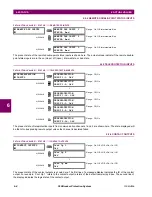
examples). The setting is entered in per-unit values. The base units are defined in the same manner as the FlexEle-
ment™ base units.
The
DCMA OUTPUT H1 MIN VAL
and
DCMA OUTPUT H1 MAX VAL
settings are ignored for power factor base units (i.e. if
the
DCMA OUTPUT H1 SOURCE
is set to FlexAnalog value based on power factor measurement).
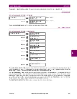
Three application examples are described below.
Example 1:
A three phase active power on a 13.8 kV system measured via UR-series relay source 1 is to be monitored by the dcmA H1
output of the range of –1 to 1 mA. The following settings are applied on the relay: CT ratio = 1200:5, VT secondary 115, VT
connection is delta, and VT ratio = 120. The nominal current is 800 A primary and the nominal power factor is 0.90. The
power is to be monitored in both importing and exporting directions and allow for 20% overload compared to the nominal.
The nominal three-phase power is:
(EQ 5.22)
The three-phase power with 20% overload margin is:
(EQ 5.23)
The base unit for power (refer to the FlexElements section in this chapter for additional details) is:
(EQ 5.24)
The minimum and maximum power values to be monitored (in pu) are:
(EQ 5.25)
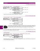
The following settings should be entered:
DCMA OUTPUT H1 SOURCE
: “SRC 1 P”
DCMA OUTPUT H1 RANGE
: “–1 to 1 mA”
DCMA OUTPUT H1 MIN VAL
: “–1.247 pu”
DCMA OUTPUT H1 MAX VAL
: “1.247 pu”
With the above settings, the output will represent the power with the scale of 1 mA per 20.65 MW. The worst-case error for
this application can be calculated by superimposing the following two sources of error:
•
±0.5% of the full scale for the analog output module, or
•
±1% of reading error for the active power at power factor of 0.9
For example at the reading of 20 MW, the worst-case error is 0.01
×
20 MW + 0.207 MW = 0.407 MW.
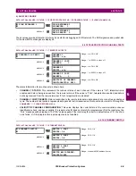
Example 2:
The phase A current (true RMS value) is to be monitored via the H2 current output working with the range from 4 to 20 mA.
The CT ratio is 5000:5 and the maximum load current is 4200 A. The current should be monitored from 0 A upwards, allow-
ing for 50% overload.
The phase current with the 50% overload margin is:
(EQ 5.26)
The base unit for current (refer to the FlexElements section in this chapter for additional details) is:
(EQ 5.27)
The minimum and maximum power values to be monitored (in pu) are:
(EQ 5.28)
The following settings should be entered:
NOTE
P
3
13.8 kV
0.8 kA
×
0.9
×
×
17.21 MW
=
=
P
max
1.2
17.21 MW
×
20.65 MW
=
=
P
BASE
115 V
120
×
1.2 kA
×
16.56 MW
=
=
minimum power
20.65 MW
–
16.56 MW
------------------------------
1.247 pu, maximum power
20.65 MW
16.56 MW
---------------------------
1.247 pu
=
=
–
=
=
0.005
±
1
1
–
(
)
–
(
)
20.65 MW
×
×
0.207 MW
±
=
I
max
1.5
4.2 kA
×
6.3 kA
=
=
I
BASE
5 kA
=
minimum current
0 kA
5 kA
------------
0 pu, maximum current
6.3 kA
5 kA
-----------------
1.26 pu
=
=
=
=
Summary of Contents for C60 UR series
Page 2: ......
Page 4: ......
Page 11: ...GE Multilin C60 Breaker Protection System xi TABLE OF CONTENTS INDEX...
Page 12: ...xii C60 Breaker Protection System GE Multilin TABLE OF CONTENTS...
Page 32: ...1 20 C60 Breaker Protection System GE Multilin 1 5 USING THE RELAY 1 GETTING STARTED 1...
Page 50: ...2 18 C60 Breaker Protection System GE Multilin 2 2 SPECIFICATIONS 2 PRODUCT DESCRIPTION 2...
Page 128: ...4 30 C60 Breaker Protection System GE Multilin 4 3 FACEPLATE INTERFACE 4 HUMAN INTERFACES 4...
Page 394: ...9 4 C60 Breaker Protection System GE Multilin 9 1 FAULT LOCATOR 9 THEORY OF OPERATION 9...
Page 516: ...D 10 C60 Breaker Protection System GE Multilin D 1 OVERVIEW APPENDIXD D...
Page 528: ...E 12 C60 Breaker Protection System GE Multilin E 2 DNP POINT LISTS APPENDIXE E...


