


5-46
C60 Breaker Protection System
GE Multilin
5.2 PRODUCT SETUP
5 SETTINGS
5
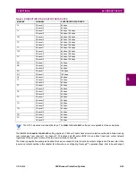
Figure 5–4: LED TEST SEQUENCE
Application Example 1:
Assume one needs to check if any of the LEDs is “burned” through user-programmable pushbutton 1. The following set-
tings should be applied. Configure user-programmable pushbutton 1 by making the following entries in the
SETTINGS
Ö
PRODUCT SETUP
ÖØ
USER-PROGRAMMABLE PUSHBUTTONS
Ö
USER PUSHBUTTON 1
menu:
PUSHBUTTON 1 FUNCTION:
“Self-reset”
PUSHBTN 1 DROP-OUT TIME:
“0.10 s”
Configure the LED test to recognize user-programmable pushbutton 1 by making the following entries in the
SETTINGS
Ö
PRODUCT SETUP
ÖØ
USER-PROGRAMMABLE LEDS
Ö
LED TEST
menu:
LED TEST FUNCTION:
“Enabled”
LED TEST CONTROL:
“
PUSHBUTTON 1 ON
”
The test will be initiated when the user-programmable pushbutton 1 is pressed. The pushbutton should remain pressed for
as long as the LEDs are being visually inspected. When finished, the pushbutton should be released. The relay will then
automatically start stage 2. At this point forward, test may be aborted by pressing the pushbutton.
Application Example 2:
Assume one needs to check if any LEDs are “burned” as well as exercise one LED at a time to check for other failures. This
is to be performed via user-programmable pushbutton 1.
After applying the settings in application example 1, hold down the pushbutton as long as necessary to test all LEDs. Next,
release the pushbutton to automatically start stage 2. Once stage 2 has started, the pushbutton can be released. When
stage 2 is completed, stage 3 will automatically start. The test may be aborted at any time by pressing the pushbutton.
842011A1.CDR
READY TO TEST
Start the software image of
the LEDs
STAGE 1
(all LEDs on)
control input is on
Wait 1 second
dropping edge of the
control input
Restore the LED states
from the software image
rising edge of the
control input
STAGE 2
(one LED on at a time)
STAGE 3
(one LED off at a time)
rising edge
of the control
input
rising edge of the
control input
Set the
LED TEST IN PROGRESS
operand
Reset the
LED TEST IN PROGRESS
operand
rising edge of the
control input
Wait 1 second
rising edge of the
control input
time-out
(1 minute)
Summary of Contents for C60 UR series
Page 2: ......
Page 4: ......
Page 11: ...GE Multilin C60 Breaker Protection System xi TABLE OF CONTENTS INDEX...
Page 12: ...xii C60 Breaker Protection System GE Multilin TABLE OF CONTENTS...
Page 32: ...1 20 C60 Breaker Protection System GE Multilin 1 5 USING THE RELAY 1 GETTING STARTED 1...
Page 50: ...2 18 C60 Breaker Protection System GE Multilin 2 2 SPECIFICATIONS 2 PRODUCT DESCRIPTION 2...
Page 128: ...4 30 C60 Breaker Protection System GE Multilin 4 3 FACEPLATE INTERFACE 4 HUMAN INTERFACES 4...
Page 394: ...9 4 C60 Breaker Protection System GE Multilin 9 1 FAULT LOCATOR 9 THEORY OF OPERATION 9...
Page 516: ...D 10 C60 Breaker Protection System GE Multilin D 1 OVERVIEW APPENDIXD D...
Page 528: ...E 12 C60 Breaker Protection System GE Multilin E 2 DNP POINT LISTS APPENDIXE E...