


GE Multilin
C60 Breaker Protection System
5-7
5 SETTINGS
5.1 OVERVIEW
5
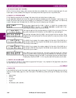
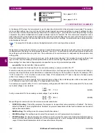
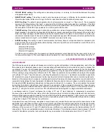
The UR platform allows for a maximum of three sets of three-phase voltages and six sets of three-phase currents. The
result of these restrictions leads to the maximum number of CT/VT modules in a chassis to three. The maximum number of
sources is six. A summary of CT/VT module configurations is shown below.
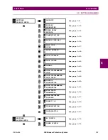
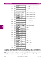
c) CT/VT INPUT CHANNEL CONFIGURATION
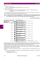
Upon relay startup, configuration settings for every bank of current or voltage input channels in the relay are automatically
generated from the order code. Within each bank, a channel identification label is automatically assigned to each bank of
channels in a given product. The ‘bank’ naming convention is based on the physical location of the channels, required by
the user to know how to connect the relay to external circuits. Bank identification consists of the letter designation of the slot
in which the CT/VT module is mounted as the first character, followed by numbers indicating the channel, either 1 or 5.
For three-phase channel sets, the number of the lowest numbered channel identifies the set. For example, F1 represents
the three-phase channel set of F1/F2/F3, where F is the slot letter and 1 is the first channel of the set of three channels.
Upon startup, the CPU configures the settings required to characterize the current and voltage inputs, and will display them
in the appropriate section in the sequence of the banks (as described above) as follows for a maximum configuration: F1,
F5, M1, M5, U1, and U5.
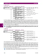
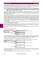
The above section explains how the input channels are identified and configured to the specific application instrument
transformers and the connections of these transformers. The specific parameters to be used by each measuring element
and comparator, and some actual values are controlled by selecting a specific source. The source is a group of current and
voltage input channels selected by the user to facilitate this selection. With this mechanism, a user does not have to make
multiple selections of voltage and current for those elements that need both parameters, such as a distance element or a
watt calculation. It also gathers associated parameters for display purposes.
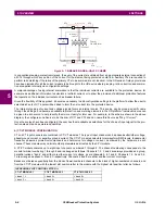
The basic idea of arranging a source is to select a point on the power system where information is of interest. An applica-
tion example of the grouping of parameters in a source is a transformer winding, on which a three phase voltage is mea-
sured, and the sum of the currents from CTs on each of two breakers is required to measure the winding current flow.
ITEM
MAXIMUM NUMBER
CT/VT Module
2
CT Bank (3 phase channels, 1 ground channel)
8
VT Bank (3 phase channels, 1 auxiliary channel)
4
Summary of Contents for C60 UR series
Page 2: ......
Page 4: ......
Page 11: ...GE Multilin C60 Breaker Protection System xi TABLE OF CONTENTS INDEX...
Page 12: ...xii C60 Breaker Protection System GE Multilin TABLE OF CONTENTS...
Page 32: ...1 20 C60 Breaker Protection System GE Multilin 1 5 USING THE RELAY 1 GETTING STARTED 1...
Page 50: ...2 18 C60 Breaker Protection System GE Multilin 2 2 SPECIFICATIONS 2 PRODUCT DESCRIPTION 2...
Page 128: ...4 30 C60 Breaker Protection System GE Multilin 4 3 FACEPLATE INTERFACE 4 HUMAN INTERFACES 4...
Page 394: ...9 4 C60 Breaker Protection System GE Multilin 9 1 FAULT LOCATOR 9 THEORY OF OPERATION 9...
Page 516: ...D 10 C60 Breaker Protection System GE Multilin D 1 OVERVIEW APPENDIXD D...
Page 528: ...E 12 C60 Breaker Protection System GE Multilin E 2 DNP POINT LISTS APPENDIXE E...


