12/222
GB
4.1.2.
only the cutting nozzle according to chart above shall be used. Nozzle-mix/injector type of the cutting
torch has to be respected as well as type of the fuel gas. use only undamaged nozzle with undamaged and
clean seat.
4.1.3.
please check also cutting torch head seat before mounting the nozzle into the cutting torch head. only
cutting torch from the list above with undamaged and clean nozzle seat can be used. Nozzle-mix/ injector
type of the cutting torch has to be respected as well as type of the fuel gas.
4.1.4. noZZLE CHooSInG
please follow the chart with cutting nozzles above. use proper nozzle size
according to metal plate thickness. gcE cutting nozzles are designed for cuts of quality level 1 according to
EN iso 9013. it is possible to reach
maximal cutting speed by set-up cutting
parameters according to chart above,
cutting of straight cuts, by using of clean
metal sheet surface, quality cutting
machine, undamaged cutting nozzle and
oxygen with purity 99,5% or better. gas
pressures are measured at the torch
inlet.
4.1.5.tightening torque of the nozzles:
Nozzle-mix cutting torch: 22-30 Nm cutting
torch Fit Mini: 22-30 Nm cutting torch bir
Mini: 12 Nm for inner cutting nozzle and
18Nm for outer heating nozzle.
noTE
: all parts in contact with oxygen should
be free of oil and grease due to explosion
hazards! check whether all threaded joints
and sealing surfaces, e. g. cones and balls,
are clean and undamaged!
4.2. FLaME IGnITIon anD SET UP
4.2.1.
check all gas connection tightness.
4.2.2.
adjust inlet gas pressures according to
the values in the table of cutting nozzles
above, see point 2.5. (1 bar = 1,05 kpa
100kpa = 105 N/m2, 1 bar = 14,22 psi). the
operating pressures for the heating oxygen
and fuel gas should be adjusted with open
torch valves. Open the fuel gas valve and
heating oxygen valve. ignite the outgoing
mixture with proper lighter supplied with the machine. With correct pressure adjustment is produced
carburizing flame. a neutral heating flame is to be adjusted with the fuel gas valve to suit the cutting task.
the heating oxygen valve remains fully open. Use a proper lighter given along with the machine to ignite the
flame. do not use hot metal or matchstick.
4.2.3.
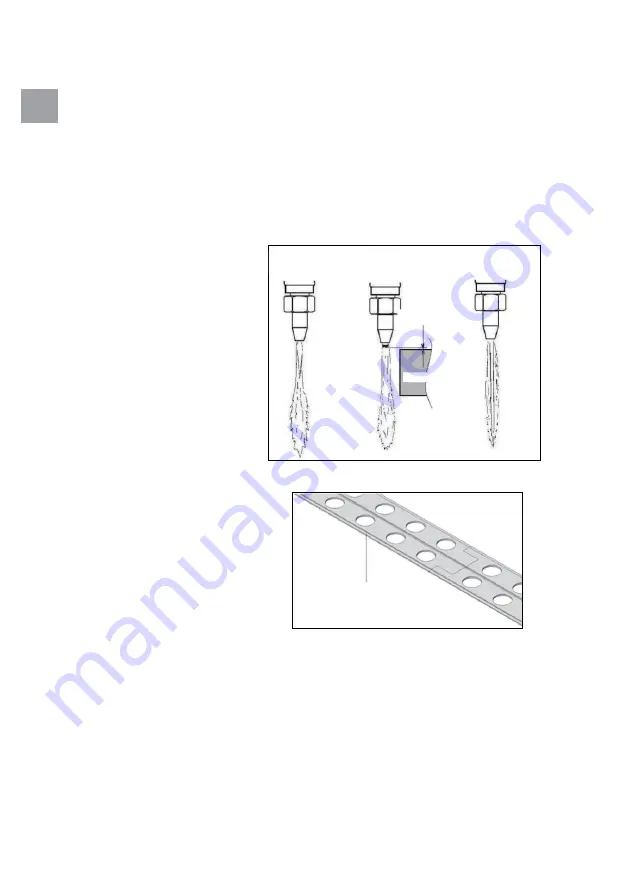
Open shortly the cutting oxygen valve to see correct adjustment of neutral flame and close it
afterwards (see also Fig.6).
4.3.CUTTInG PRoCESS InITIaTIon
Bring the torch to the initial cutting position and start locally heating the workpiece to the ignition
temperature, approximately bright red / yellow colour. then open the cutting oxygen valve and switch on
the feed in the same moment.
4.4. THE CoRRECT CUTTInG SPEED
can be seen from the slag production, from the
Fig.7: Zn coated track extension
almost vertical spray of sparks
and from the cutting noise. the approximate values of the cutting speed can be taken from relevant cutting
nozzle table as above.
Fig.6: Flame adjustment
Carburazing fl
ame
during ignitin
g
Neutral flame
Neutral flame wit
h
cutting oxygen jet
approx. 1 mm
Workpiece
Straight
edge
Summary of Contents for proFIT
Page 3: ......
Page 46: ...46 222 CZ...
Page 55: ...55 222 CZ ovl dac panel 240 v ov l dac panel 110 v ovl dac panel 240 v 240 v 110 v...
Page 56: ...56 222 Obr 13 Zm na nap t 240V 110V...
Page 106: ...106 222 ES...
Page 114: ...114 222 Fig 13 Cambio de voltaje 240V 110V 7 diagrama de la conexi n el ctrica...
Page 128: ...128 222 PT...
Page 166: ...166 222 RU...
Page 167: ...167 222 a 3 10 g1 4 g3 8 LH...
Page 172: ...172 222 11 1 2 3 6 7 M6x20 8 9 10 4 1 5 6 7 8 9 11 2 5 gcE proFIT 12 12 RU 240 10...
Page 173: ...173 222 5 5 1 gcE proFIT shell vitrea 31 5 2 5 3 RU 110 v 240 v 110...
Page 174: ...174 222 13 240 110 gcE proFIT...
Page 175: ...175 222 6 240 110 13 RU 7 8...
Page 176: ...176 222 9 9 1 gcE proFit 9 2 9 3 9 4 10 10 1 RU Bild 14 Exempel p inpackning...
Page 177: ...177 222 10 2 10 10 3 11...
Page 178: ...178 222 12 14 3 50 c 130 F en 730 1 en 560 14008408 g3 8 RU 13...
Page 179: ...179 222 14008263 g1 4 14008278 g3 8 LH RU...
Page 180: ...180 222 c...
Page 221: ......


