Instructions for DKC500ACL/DKC800ACL
www.gatexpertstore.com
17
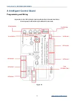
Potentiometer Adjustment
All changes to these settings must be completed by a licensed electrician
Figure 18
VR1: Stall Force Mode
Maximum = More Force = Less sensitive
Minimum = Less Force = More sensitive
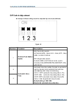
When Stall Force Mode is enabled (Dip switch 5 is at OFF position), the gate opener will
detect obstacles and impacts to the gate. If this is during opening, the gate will stop, if this is
during closing the gate will stop, and then re-open. Rotate VR1 clockwise to increase the
stall force, anti-clockwise to decrease.
For safety, we strongly recommend that Stall Force Mode is left enabled (Dip switch
5 is at the OFF position). Do not turn Dip switch 5 to the ON position.
VR2: Brake Force Adjustment
For adjusting brake force at the limit position during gate opening and closing. This should
only be adjusted for heavy gates that need additional force to brake when limit switch is
detected.
Rotate VR2 clockwise to increase, counter-clockwise to decrease. Default setting is at
minimum.
VR3: Slow Start/Stop Width Adjustment
This switch controls how many seconds the gate opener operates at maximum speed.
Rotate VR3 clockwise to increase, rotate counter-clockwise to reduce.
When VR3 switches to minimum, slow start/stop function is disable.
VR4: Motor Output Force Adjustment
For best performance, set the torque at the lowest setting for secure use.
Rotate clockwise to increase, counter-clockwise to decrease.
Default setting is at maximum.


