


22
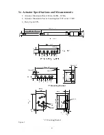
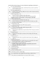
11.
Advanced
Control
Wiring
F1
‐
fuse
(maximum
0.5A)
PCB
F2
‐
fuse
(maximum
15A)
Over
current
J1
‐
1&2
MM1
Master
gate
J2
‐
3&4
SM2
Slave
gate
J3
‐
5&6
Electric
lock,
12VDC,
Max
current
5A
J3
‐
7&8
Flashing
light.
12VDC,
Max
power
21W
J4
‐
9
Positive
Supply
12V
DC
J4
‐
10
use
with
12
Keypad
/
Pushbutton
for
the
dual
gate
operation
J4
‐
11
use
with
12
Keypad
/
Pushbutton
for
the
single
gate
operation
J4
‐
12
Logical
and
Power
Ground
for
external
devices
J4
‐
13
Positive
Supply
12V
DC
J4
‐
14&15
Photo
sensor
contacts,
must
be
shorted
together
if
no
photocell
J5
‐
16
Aerial
Antenna
cable
(Connect
to
Aerial
for
increased
range)
J6
‐
Reset
Switch
SW2
‐
This
button
is
used
for
code
learning.
VR1
‐
Over
current
limit
can
be
adjusted
from
min
3.5Amp
to
Max
7.5Amp
VR2
‐
Close
delay
can
be
adjusted
from
min
0
second
to
Max
8
second